SYNERGY
A visual,
activation and propagation-based
multi-paradigm
programming language based on
Executable
Conceptual Graph
by
Adil KABBAJ
1. Introduction
3.1. Primitive concept types and
primitive relation types of Synergy
3.2.1 Expression
3.2.2 Sequence
3.2.3 Parallelism
3.2.4 Conditional Code
3.2.5 Iteration
3.3. Defined
Concept Type
3.3.1 Parameters and Arguments
3.3.2 Operation vs Process
3.3.3 Recursion
3.3.4 Example of defined concept type
3.4 Concept state and Concept
life-cycle
3.5 Propagation rules for
Data/Control relations
3.6 CG activation mechanism and the interpreter of SYNERGY
3.6.1 Concept-life cycle: complement
3.6.2 Parallelism
and the Synergy interpreter
3.8 Procedural vs Functional interpretation
of Synergy relations
3.9 Control of Forward/Backward
propagation
4. Checking
Functional Dependency
5. Call
Java (Methods) from Synergy
5. Calling
Synergy from Java (Code)
6. Calling
Synergy from other components of Amine
7. Dynamic
Programming in Synergy
8. Automatic
composition of web services with Synergy (since Amine 9) ![]()
9. Synergy GUI
10. Synergy
vs CharGer: A brief comparison
11. Interoperability
between Synergy and CharGer
13. Limitations
14. References
Synergy is a visual,
activation and propagation-based multi-paradigm programming language based on
executable Conceptual Graph
(CG). Execution is based on a CG-activation mechanism for which concept lifecycle, relation propagation rules and designator instantiation operation constitute the
key elements. Synergy has been designed and developed by Adil Kabbaj in his
Ph.D. thesis (1992-1996).
We
proposed CG activation-based mechanism as a computation model for executable
conceptual graphs [7-10]. Activation-based computation is an approach used in
visual programming, simulation and system analysis where graphs are used to
describe and simulate sequential and/or parallel tasks of different kinds:
functional, procedural, process, event-driven, logical and object oriented
tasks. Activation-based interpretation of CG is based on concept lifecycle,
relation propagation rules and referent/designator instantiation. A concept has
a state (which replaces and extends the notion of control mark used by Sowa)
and the concept lifecycle is defined on the possible states of a concept.
Concept lifecycle is similar to process lifecycle (in process programming) and
to active-object lifecycle (in concurrent object oriented programming), while relation
propagation rules are similar to propagation or firing rules of procedural
graphs, dataflow graphs and Petri Nets.
SYNERGY
is a visual multi-paradigm programming language based on CG activation
mechanism. It integrates functional, procedural, process, reactive,
object-oriented and concurrent object-oriented paradigms. The integration of
these paradigms is done using CG as the basis knowledge structure, without
actors or other external notation. Previous versions of Synergy have been
presented [6, 7]. The integration of Synergy in Amine required a re-engineering
work and some changes and extensions to the language and to its interpreter.
New features of Synergy include:
·
Long-term memory introduced in previous definitions of
Synergy corresponds now to ontology that plays the role of a support to a
Synergy “expression/request”,
·
Previous versions of Synergy did not have an interface
with Java. The new version of Synergy includes such an interface; Java objects
can be created and methods activated from Synergy. This is an important feature
since user is not restricted to (re)write and to define anything in CGs. Also,
primitive operations are no more restricted to a fixed set of operations.
·
The new version of Synergy has an access to the two
first layers of Amine. Also, since all the components (Prolog+CG, Synergy,
dynamic ontology formation process, etc.) are integrated in the same platform
and share the same underlying implementation, it is now possible to develop
applications that require all these components. We provide an example of this
possibility in the next section.
·
The new version has an interface with Java: Java
objects and methods can be created/used from Synergy programs.
·
Another new feature is the possibility to perform dynamic
programming, i.e. dynamic formation-and-execution of the program. We focus
on this feature in section dynamic_programming.
·
Other new features are introduced in this document.
Conceptual
Graph (CG) theory is proposed by Sowa [18, 19] as a graphic system of logic and
as a CG Interchange Format (CGIF) [21]. In [19], Sowa notes that many popular
diagrams (e.g., type hierarchies, dataflow diagrams, state-transition diagrams,
Petri-Nets, etc.) can be mapped to CG and in [20] he proposes CG as a logical
foundation for object-oriented systems. Thus, CG is presented by Sowa as a
formalism for the representation of knowledge (both declarative and procedural)
with a logical interpretation; execution should be done with proof techniques
of logic using rules of inference. Other CG execution mechanisms have been
proposed in literature [1, 3, 4, 7, 13, 14, 15, 16].
In
[7, 8] we proposed CG activation-based
mechanism as a computation model for executable conceptual
graphs. Activation-based computation is an approach used in visual programming,
simulation and system analysis where graphs are used to describe and simulate
sequential and/or parallel tasks of different kinds: functional, procedural,
process, event-driven, logical and object oriented tasks [2, 11, 12, 17,
23, 24].
Activation-based
interpretation of CG [7, 8] is based on concept lifecycle, relation propagation rules and
referent/designator instantiation. A concept has a state (which
replaces and extends the notion of control mark used by Sowa [18]) and the concept
lifecycle is defined on the possible states of a concept. Concept lifecycle
is similar to process lifecycle (in process programming) and to active-object
lifecycle (in concurrent object oriented programming), while relation
propagation rules are similar to propagation or firing rules of procedural
graphs, dataflow graphs and Petri Nets [8]. Since 1995, we have designed and
implemented a visual language, called SYNERGY that is based on such an
activation mechanism. SYNERGY is a visual
multi-paradigm programming language; it integrates functional, procedural,
process, reactive, object-oriented and concurrent object-oriented paradigms.
The integration is done using CG as the basis knowledge structure, without
actors or other external notation.
SYNERGY
is designed for visual programming, modeling and simulation. It can be used for
different purposes and in many fields: programming languages, simulation,
database, information systems, software engineering, knowledge acquisition,
knowledge base systems, intelligent tutoring systems and multi-agent systems.
SYNERGY has been used for the development of a concurrent-object oriented
application (e.g., a visual agent-oriented modeling of the Intensive Care Unit)
and in modeling some components of an intelligent tutoring system [9]. It has
been used also for the specification of a multi-agent system [25]. A hybrid
object-oriented use of Synergy is illustrated in [10].
First
implementation of SYNERGY has been done in C++ by Adil Kabbaj with the
collaboration of Khalid Rouane (1995-1996). A reformulation of Synergy
interpreter in Java has been done by Adil in the period 1998-2000. However, for
the integration of SYNERGY in Amine platform, the previous reformulation had to
be debuged and adapted. This work has been done for the Core of Synergy, by
Adil Kabbaj with the help of Said Ladib. Other aspects of Synergy are being
considered by Adil and Said.
SYNERGY
has been presented through five papers, submitted to previous ICCS conferences
:
1.
Contexts, Canons and
Coreferences as a basis for a multi-paradigm language : This paper shows how basic elements
of CG theory, like CG structure, canon, context and coreference constitute the
basis for the multi-paradigm language SYNERGY. For computational purpose, a)
the definition of coreference is extended to include compound coreference, b) states
and lifecycles are
associated to concepts and c) a finite set of data
and control relations (in, out, guard,
next) are defined with propagation rules as
their procedural semantic. Computation model of SYNERGY corresponds to a
context activation mechanism which is based on
concept lifecycle and
relation propagation rules.
2.
Synergy : A Conceptual
Graph Activation-Based Language: This paper presents the Core of Synergy: the CG
structure (concept, relation, context, co-reference) and the activation
mechanism used in Synergy as well as the concept type definition, the
encapsulation mechanism and the knowledge base of Synergy. Examples are given
to illustrate some aspects of the language.
3.
SYNERGY as a
concurrent object oriented language: This paper presents the concurrent object oriented
model embedded in SYNERGY and an application that illustrates this use of the
language. Basic features of the SYNERGY concurrent object oriented model are:
1) an active object, with its message queue, its declarative part and its
procedural part (script + body) is described as a labeled context, 2) both
“coupled” communication mode (objects communicate
directly with one another by sending/receiving messages)
and “non-coupled” communication mode (objects share and communicate information via a common
space) are provided, 3) objects types form a hierarchy used by inheritance
mechanism and, 4) both inter- and intra-concurrency are provided; several
objects can be active in parallel and several methods of an object can be
executed in parallel. This paper shows also that the integration to SYNERGY of
the concurrent object oriented model is based on the use of key elements as CG
structure, contexts and coreferences.
4.
Synergy as an Hybrid
Object-Oriented Conceptual Graph Language: This paper presents the use of
Synergy as an Hybrid Object-Oriented Conceptual
Graph Language (HOO-CGL). It describes the formulation in Synergy of basic
concepts of the hybrid object-oriented paradigm: encapsulation, definition of a
class with methods and daemons, method and daemon definitions, class hierarchy,
instance and instantiation mechanism, inheritance (both property and method
inheritance), method call, method execution and daemon invocation due to data
access. An example is used to illustrate the presentation of such an Hybrid
Object-Oriented Conceptual Graph Language.
5.
Development of
Intelligent Systems with Amine: This paper presents an overview of Amine. A
section of this paper introduces Dynamic Programming in Synergy. See Dynamic Programming for more
detail.
Full
integration of SYNERGY in Amine is being performed in five steps:
1.
Integration of the Core of SYNERGY,
2.
Integration of interface with Java and of Dynamic
Programming in Synergy
3.
Extension of the Core with the treatment of compound
coreferences,
4.
Integration of Object Oriented SYNERGY,
5.
integration of Concurrent Object Oriented SYNERGY.
Integration
of the Core of SYNERGY to Amine is finished (but test and debug continue !).
The current document introduces this work. It presents also the implementation of
the second step: Integration of interface with Java and of Dynamic Programming
in Synergy. Next versions of this document will report the progress concerning
the implementation of the other steps, with examples and other details.
A
procedural knowledge (action, operation, function, expression, procedure,
process, task, etc.) can be represented by CG. Execution/Interpretation of
procedural knowledge corresponds to the execution/interpretation of CG. To
enable this extension of CG, we have extended the standard interpretation/view
of concepts and relations (of a CG): a concept can represent both a static
and/or a dynamic (or active) entity. Thus, primitive operations like
arithmetic, relational and logical operations can be represented as concepts.
Also, a relation can be used to establish a static/descriptive structure and/or
to establish a procedural/control structure.
Primitive concept types and primitive relation types of
Synergy
The
type of a concept can be
a
defined
concept type or
a primitive concept type (primitive data type
like Int, Real, Number, Boolean, String, or a primitive
operation type: Add, Sub, Mul, Div, Sqrt, Assign, Equal, Dif,
NotEq, Inf, Sup, InfEq, SupEq, And, Or, Not, Read, Write, etc.).
Like Prolog+CG, Synergy provides a very small set of
primitives. This is not really a limitation because Synergy provides, via Calling Java objects/methods from
Synergy, a means to use an infinity of operations/methods, including
all methods offered by Amine platform.
Beside the
primitive data and operation types, Synergy provides a set of procedural relations
= {“in”, “out”, “grd”, “next”}. "in"
and "out" are data relations
(they relate income and outcome arguments to the operation) while
"grd" and "next" are control
relations ("grd" relates a condition to an operation
and "next" imposes a sequential execution of two operations).
Note: in each of the following statements, C and C’
represent respectively the source and the target concepts of the relation in
question.
C
—in-> C’ : C is an income argument for C’.
C
—out-> C’ : C has C’ as an outcome argument.
C
—grd-> C’ : C is a precondition for the execution of C’.
C
—next-> C’ : After the execution of C, execute C’.
Like
Lisp language, Synergy provides a set of primitives and also a possibility to
define new types (that represent functions or procedures or processes). Also,
like Lisp, Synergy is interactive: user formulates requests (represented by CG)
and Synergy interpreter attempts to evaluate and get an answer to these
requests.
Primitives
concept types and primitives relation types constitute "Synergy
Ontology". This ontology (of primitives) is automatically loaded by
Synergy Interpreter. Defined concept types are defined in an ontology and of
course such an ontology should be loaded to enable the edition and the
execution of the request.
See
examples below and See Synergy GUI for
more detail.
Examples:
Note:
Examples below are illustrated with "Amine proper LF/CGIF notation"
adopted by versions of Amine previous to Amine 6. With Amine 6.0, these
examples work also with Standard CGIF notation.
Figure
1 shows the graph/visual formulation of the following code (composed of two
affectations):
z = 4 * 7;
r_result = x * y + z - 1;

Figure 1:
Formulation of an expression (a request)
Figure
1 illustrates the fact that concepts represent (primitive) data types as well
as (primitive) operations. Figure 1 illustrates a request that corresponds to
an expression (represented as a CG). Synergy interpreter will execute the
expression by CG activation. The detail of the execution/activation is
presented below.
Note:
Since Amine 6.0, once Synergy GUI is activated, Synergy ontology that contains
primitive types is automatically loaded. So, if only primitive types are used
in the program/request, then the user can edit/execute his program/request
without any load of any ontology. However, if his program/request contains
defined concepts, then he should load first the appropriate ontology where the
types are defined.
The
sequence of operations execution is implicit,
determined by dependency between operations, and explicit,
determined by the use of "Next" relation. Examples in this document
illustrate various forms of Sequence.
The
default control structure in Synergy is (simulated) parallelism, not sequence.
Depending on data/control dependency, concepts (that represent operations,
functions, procedures, processes) can be executed/activated in parallel.
Examples in this document illustrate this basic feature of Synergy. See Parallelism in Synergy
for complement details.
"Grd"
(guard) relation is a primitive relation that can be used to express conditions
on operations/functions/procedurses. Figure 2 shows the graph/visual
reformulation of a conditional instruction (if-then-else) in terms of Grd
relations:
if
(x < y)
z = x + y
else
z = x - y.
Note:
The result of a function can be assigned to an explicit outcome argument or to
the function itself, as illustrated by Figure 2.b. The two formulations (in
Figure 2.b) are equivalent.


(a)
(b)
Figure 2:
Formulation of a conditional instruction
Like conditional instruction,
Iteration can be expressed using Synergy relation primitives (especially Grd
and Next). As an example of iterative code, consider the iterative (non
recursive) definition of the function factorial (it is provided in the ontology
"samples/ontology/synergyOntology/ontology1.xml").
The detail of the definition as well as the detail of its execution/activation
are considered in Execution/Activation of Iterative
Code.
int IterativeFactorial(int i) { // for i > 0
x := 1;
y := 1;
while (x < i) do {
x := x + 1;
y := x * y;
}
return y;
}

Figure 2Bis:
Formulation of an iteration
The
type of a concept in a CG can be defined; defined by the user
in an ontology.
Parameters and Arguments:
If the
concept type is defined
and represents a treatment with arguments, then the
corresponding parameters should be specified in the definition of the type. In Synergy, the designator of an income parameter should
be prefixed by "inX" where X
stands for an optional integer that specifies the range of the income parameter
(an example of
an income parameter: [Integer
in3:y]; this concept represents the third
income parameter in the definition of the concept type). The designator of an outcome parameter should
be prefixed by "outX" (an example of an outcome parameter: [Integer out2:z]; this concept represents the second
outcome parameter in the definition of the concept type).
In
general and as discussed below, an activation of a concept with a defined type
and a null descriptor will involve an instantiation
of the type definition: a copy of the definition is created and
assigned as a descriptor for the concept. Then, state
of parameters in the definition are initialized to state "trigger"
and parameters will refeer to their
corresponding arguments (we adopt a transmission by address, between arguments
and parameters).
Operation vs Process:
If the defined type represents a treatment, then the user should specify
the concept [Operation :super] or [Process :super] in its
definition to indicate how the type should be interpreted: if the concept [Operation :super] is specified, then once
the operation terminates its execution, its description is destroyed as the
case for the “record activation” of a procedure in procedural programming. However, if the concept [Process :super] is specified, its description is
not destroyed (after the end of its execution/interpretation).
If no one of the two is
specified, the treatment is interpreted as a process, by default.
Recursion: Recursive definition
of a concept type
Synergy
considers the case of concept type with recursive definition. The example of
recursive definition of Factorial is described and discussed below (RecursiveFactorial).
Example of defined concept type
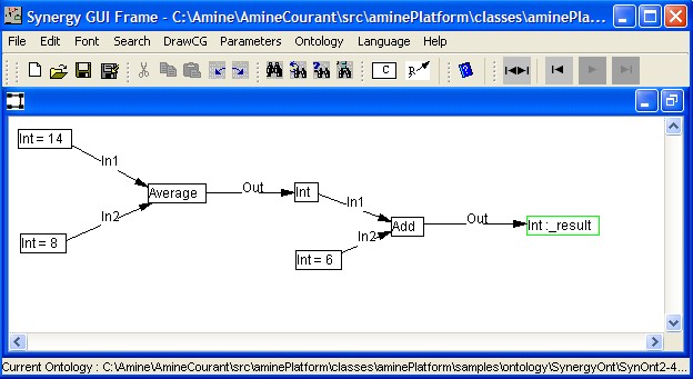
Figure
3 shows an example of a defined type; the definition of the function Average
(Figure 3.a) and an example of a call to this function in an expression/request
(Figure 3.b). To run this example, load first the following ontology: "aminePlatform/samples/ontology/synergyOntology/ontology1.xml".
The expression/request that contains the call to Average is stored in the file
"aminePlatform/samples/synergy/expleDefConcType.lnf". So you
can open this file to edit and execute the expression/request.
The
concept type Average has two income parameters and one outcome parameter. Since
the concept [Operation:super] is specified in the definition of
Average, then once the concept [Average] terminates its execution, its
description is destroyed. A new activation of the concept [Average] will
involve the creation of a new description (by definition instantiation). If [Process:super] was specified (instead of [Operation:super]), then upon the termination of the
execution of the concept, its description will not be destroyed. A new
activation of the concept will use the same description.
The
detail of the activation/execution of this example is described and discussed
below; in the next section.
(a) 
(b) 
Figure 3: Definition
of the concept type "Average" and a "call" to this concept
type in an expression
Concept state and Concept life-cycle
Beside
concept type, concept designator and concept descriptor, a concept (in SYNERGY)
has a state. The state field of
a concept is defined on the following set: {steady,
trigger, check-preconditions, wait-preconditions, wait-value, in-activation,
wait-affectation, wait-end-affectation}. This set enumerates the
possible states of a concept. Each state of a concept has a visual
representation. For instance, the rectangle (that encloses a concept) is green
if the concept state is “trigger” and it is red if the state is
“in_activation”. See Synergy GUI
for the visual representation of the other states.
The
dynamic of a concept is described according to the concept life-cycle (which is a transition
network), defined on the possible states of a concept. Concept life-cycle is
introduced below.
Concept
life-cycle
Concept
life-cycle is a state
transition diagram (Figure
4) where states correspond to the possible states of a
concept and transitions to the conditions/actions on the concept and on the
data/control relations linked to the concept.

Figure 4: Concept’
life-cycle
A concept C in “trigger” state is asked "to determine its descriptor and attempt to activate/execute/interpret it". The concept C can have already a descriptor, or its type is a primitive operation type (with a built-in interpretation), or its type is defined and in this case the descriptor will be determined by definition instantiation (i.e. a copy of the definition body). If none of these possibilities hold, the interpreter will attempt to compute the descriptor by backward propagation (through the “out” relation) and the concept C becomes at state “wait-value” (wait for the creation/computation of its descriptor).
Once C has a descriptor or its type is a primitive operation type, its state
changes from “trigger” to “check-preconditions”; the state where the concept C should check its
preconditions (e.g., a
concept C’ is a precondition for another concept C
if C' is an income
argument for C or it is a guard condition: C’ —in®
C or
C’ —grd® C). The
concept C’ that represents a precondition for the concept C can be triggered
(by backward propagation through the “in” or “grd” relation) and C changes its
state to “wait-preconditions”. Of
course, a concept C can have no precondition.
If all the pre-conditions are satisfied, C changes its state from
“check-preconditions”
to the state “in-activation” and its description is activated/executed/interpreted: if
the type of C is a primitive operation then the primitive is executed. If the
description of C is a CG then the CG is executed (in parallel to other active CGs). If the description is a primitive data (like an integer
or a string) then its execution is "null" (i.e. it
takes no time and it has no effect).
If
the activation of the description is terminated and the concept has no assignment
post-conditions, then the concept C returns to the “steady” state. Assignment
post-conditions
will be considered later.
Concept
life-cycle, as described above, constitutes the kernel of CG activation and Synergy
Interpreter.
Propagation rules for Data/Control relations
Currently,
relation
propagation rules apply only to data and control relations as well as to co-reference
link (viewed as a “virtual” data relation between a bound node C1 and its
defining node C2: C1 –coref®
C2. Co-reference link
will be considered in next versions of this document). A data/control
relation can propagate a concept
state forward (from the source to the target concept of the relation)
and/or backward (from the target to the source of the relation).
Forward propagation rule. If an active context contains a branch
C1 –Rel® C2 where the state of C1 is “trigger” and Rel Î
{"in", "out", "next", "coref"} then the relation Rel will propagate
forward the state “trigger” to the concept C2. If Rel = “grd” then the
propagation will be done only if the description of C1 is different from
“false”.
Backward
propagation rule. If an active context contains a branch C1 –Rel® C2 where the state of C2 is
“trigger” and Rel Î
{"in", "out", "grd", "coref"} then the relation Rel will propagate
backward the state “trigger” to C1 if one of the following conditions is
satisfied:
- Rel
= "in" and C1 is at state “steady” and it hasn’t a description.
- Rel
= "out" or "coref" and C2 hasn’t a description, its type
isn’t a primitive operation and it isn’t defined (e.g., its description cannot
be determined by instantiation).
- Rel
= "grd" and C1 is at state “steady” and it hasn’t a description.
Concept
life-cycle with propagation rules for data and control relations, constitute
the kernel of CG activation and Synergy interpreter.
CG
activation mechanism and the interpreter of SYNERGY
SYNERGY
interpreter is based on CG (or context) activation/execution.
CG (context) activation
begins with parallel interpretation
of concepts of the CG,
then data and control relations (if they are present) spread or propagate concept's parallel activation
through the CG.
Interpretation of a concept is done according to its life-cycle while the spreading activation is performed according
to relation propagation rules.
SYNERGY
interpreter starts with the interpretation of the working
memory context; the first active
context
that contains the user requests (represented as CGs). An interpretation/activation of a
concept with a primitive type involves the execution of the primitive. An
interpretation/activation of a concept with a defined type will involve (in
general) an instantiation of its definition and an interpretation/activation of
this instantiation, producing a new active context, and so on. Hence, SYNERGY
interpreter is concerned by a parallel interpretation of several active contexts
and/or the execution of several primitive operations. The association of
a state and a life-cycle to a concept enables the interpretation and management of such a parallelism.
In effect, each concept is interpreted (e.g., evolves, changes) according to
its state and to its life-cycle; the
activation (or interpretation) of an
active context is thus decentralized.
Concept-life cycle: complement
In
our description of concept life-cycle,
we specified that at the end of a concept activation, assignment
post-conditions should
be considered, without providing detail on these conditions. This section fills this gap. Three kinds of
post-conditions are possible:
1.
2. Even if all the
values computed by C can be assigned to their corresponding outcome arguments,
C can still wait due to a "conflict of affectations" that can occur
when several concepts attempt, at the same time, to affect values to the same
concept. In this case, C will change its state to
"wait-for-end-of-affectation ; @nda".
3. If the concept
C has terminated its activation and has satisfied the above assignment
post-conditions (if it has) and if it is related to a concept C1 (C
–Rel-> C1) with Rel defined on {"in", "out",
"grd", "next", "coref"} and without the
cut_forward_propagation attribute
">|", then the forward propagation rule of Rel is applied.
Parallelism
and the Synergy interpreter
As noted in
previous sections, Synergy interpreter should manage parallel activation of several contexts (CG) and/or the
execution of several primitive operations. Each concept is interpreted (e.g., evolves, changes)
according to its state
and life-cycle,
the activation (or interpretation) of a
context is thus decentralized.
As a parallel language, Synergy enables the user to write parallel programs,
its interpreter is able to execute those programs and its graphical user interface (GUI)
allows the user to see and debug the
parallel activation of those programs. This “conceptual parallelism” is at the
design/language level. It can be implemented on a parallel machine (e.g.,
“physical parallelism”) or it can be interpreted and simulated on a sequential
machine. In
our current implementation of Synergy, we have considered the second option. Some
constraints have been assumed, especially for parallel execution of primitive
operations. For instance, we assumed that during the execution of a primitive,
no interaction could occur between the primitive and the other parts of the
Synergy “program”.
Note: Examples below are illustrated with
"Amine proper LF/CGIF notation" adopted by versions of Amine previous
to Amine6. With Amine 6.0, these examples work also with Standard CGIF
notation.
Example #1: Expression execution/activation
Let
us consider the activation of the expression formulated in Figure 1. State of the concept [Int=4] has been
initialized to "trigger" (Figure 5). Consult Synergy GUI for the detail on the use of
this GUI and how to create, open and use a Synergy application. The main frame
of Synergy GUI is the working memory WM
(working space) where requests are
formulated. The CG file that contains the request is "samples/synergy/exple_expression.lnf"
(there is also a CGIF version of this request).
Synergy
interpreter attempts to interpret (to activate or execute) the content of the
WM. In our case, the WM contains one request which corresponds to an
expression. Note also that Synergy GUI provides facilities to execute the
content of the WM at once or step-by-step (Figure 5). The latter enables the
user to "see" and to follow the activation of CGs (that constitute
the content of the WM).

Figure
5:
Activation of the expression I
Concept
[Int = 4] is a primitive data concept, so its activation is "null".
However, forwad propagation of its state ("trigger") has been done to
the concept [Mul] through relation "in1" (Figure 6.a). Concept [Mul]
is a primitive operation, i.e. its activation involves the activation of the
primitive. Note that the state of the concept [Mul] changed from
"trigger" to "in-activation" (Figure 6.b) because all its
preconditions are satisfied (in this case, its two income arguments have
value). Execution of a primitive operation takes one Synergy cycle (i.e. one
step). So in the next step, the primitive concept like [Mul] will terminate its
execution/activation.


Figure
6:
Activation of the expression II
After
the termination of the activation of the concept [Mul], the result is assigned
to the concept [Int:z] which becomes [Int :z = 28]. Due to the change in its
descriptor, the state of the concept [Int :z = 28] changed to
"trigger" (Figure 7.a). Its state is then propagated to the concept
[Add] through the relation "in2" (Figure 7.b).


Figure
7:
Activation of the expression III
Concept
[Add] represents a primitive operation. Since its first income argument has not
a value (Figure 7.b), its state changed from "trigger" to
"wait-preconditions" (Figure 8.a). At the same time, the state of its
first income argument (concept [Int]) changed to "trigger" (Figure
8.a). Since the concept [Int] represents a primitive data, it has not a value
and it is an outcome argument of the concept [Mul], then its state
("trigger") is propagated to the concept [Mul] (Figure 8.b). The
state of the concept [Int] changed from "trigger" to
"wait-value" (Figure 8.b).


Figure
8:
Activation of the expression IV
Concept
[Mul] is ready for activation, since all its pre-conditions are satisfied (in
this case, its two income arguments have value). The concept [Mul] changes its
state to "in-activation" (Figure 9.a). Once its execution terminated
(it takes one Synergy cycle), the returned value is assigned to the outcome
argument [Int] which becomes [Int = 72]. Due to this assignation, the state of
this concept changed from "wait-value" to "trigger" (Figure
9.b).


Figure
9:
Activation of the expression V
Concept
[Add], that was in state "wait-preconditions", changes its state to
"in-activation" (Figure 10.a) since all its pre-conditions are (now)
satisfied (in this case, its two income arguments have value). After the
termination of its execution, the returned value is assigned to its outcome
argument (Figure 10.b) which becomes at "trigger" state, with
descriptor 100: [Int = 100].


Figure
10:
Activation of the expression VI
The
state "trigger" of the concept [Int = 100] is propagated to the
concept [Sub] (Figure 11.a) and since all its pre-conditions are satisfied, its
state changes to "in-activation" (Figure 11.b) and the primitive
operation is performed.


Figure
11:
Activation of the expression VII
The
result of [Sub] is assigned to its outcome argument [Int :r_result] which
becomes [Int :r_result = 99] with state "trigger". The concept [Int
:r_result = 99] changes then its state to "steady" with no effect
(since it is not related to other concepts and so, its state cannot be
propagated to other concepts). Figure 12 shows the end of the execution: the
content of the Working Memory is no more active.

Figure
12:
Activation of the expression VII
Example #2:
Let us consider now the activation of the conditional instruction formulated in
Figure 2. This example illustrates the use of
"grd" (guard) relation to express conditions on the activation of
operations (i.e. primitive or defined treatment) and illustrates also backward
propagation. Figure 13.a shows the CG that represents the conditional
instruction: condition x < y is a guard for the operation x + y, i.e.
this operation can be activated only if the condition (x < y) is satisfied.
The operation x - y is conditioned by the negation of (x < y). Activation of
this conditional instruction is initiated by putting the concept [Int: z] in
state "trigger" (Figure 13.a). Then, by backward propagation, through
"out" relations, operations [Sub] and [Add] are triggered, in
parallel, and the concept [Int: z] changes its state to "wait-value"
(Figure 13.b).
The
CG file that contains the request is: "samples/synergy/exple_if.lnf"
(there is also a CGIF version of this request).


Figure
13:
Activation of a conditional instruction I
Both
[Sub] and [Add] have a pre-condition: [Not] is the guard for [Sub] and [Inf] is
the guard for [Add]. The two guard have not a value. Thus, the
"trigger" state is propagated, backward, to [Not] and [Inf]. Then,
concepts [Sub] and [Add] change their states to "wait-preconditions"
(Figure 14.a). All the pre-conditions of the concept [Inf] are satisfied (i.e.
its two income arguments have value), so its state changes from
"trigger" to "in-activation" (Figure 14.b) and the
primitive operation (<) is initiated. Its execution will take one Synergy
cycle (one step). The operation [Not] cannot be activated immediatly however;
it should wait for the value of its income argument.


Figure
14:
Activation of a conditional instruction II
The
execution of (6 < 4) returns false (Figure 15.a) which is assigned to the
descriptor of the concept [Inf] (since its outcome argument is not specified;
the operation will play the role of its outcome argument). Now, the operation
[Not] can change its state from "wait-preconditions" to
"in-activation" (Figure 15.b) since its income argument has now a
value (it was the only pre-condition for [Not]). Note that the operation [Add]
remains in state "wait-preconditions" since its precondition is not
satisfied. In fact, [Add] will remain in the state "wait-preconditions"
until the end of the execution.


Figure
15:
Activation of a conditional instruction II
The
execution of the operation [Not] returns true which is assigned to [Not] itself
(Figure 16.a). The operation [Sub] is no more blocked; it will change its state
from "wait-preconditions" to "in-activation" (Figure 16.b)
since the condition, represented by the concept [Not], is satisfied.


Figure
16:
Activation of a conditional instruction III
The
execution of the operation [Sub] returns the value 2 which is assigned to the
concept [Int:z] that becomes [Int :z = 2] with state "trigger"
(Figure 17).

Figure
17:
Activation of a conditional instruction IV
Concept
[Int :z = 2] changes its state from "trigger" to "steady"
without effect and the activation of the WM is finished (Figure 18).

Figure
18:
Activation of a conditional instruction V
Example #3:
Let us consider now the activation of an expression that contains a defined
operation Figure 3. This example illustrates the
activation of a concept with defined type. The activation of the content of the
WM is initiated by setting the state of the concept [Int: _result] to
"trigger" (Figure 19).
To
run this example, load the ontology "samples/ontology/synergyOntology/ontology1.xml".
Then open the CG file that contains the request ("samples/synergy/expleDefConcType.lnf").
Figure
19:
Activation of an expression that contains a defined operation I
The
state of the concept [Int: _result] is propagated backward to the concept
[Add], through the relation "out", and the concept [Int: _result]
changes its state to "wait-value" (Figure 20.a). The concept [Add]
changes its state to "wait-preconditions" (Figure 20.b) since its
first income argument has no value. The latter (the concept [Int]) changes its
state to "trigger" (Figure 20.b). Next, the state of the concept
[Int] is propagated backward to the concept [Average], through the relation
"out", and the concept [Int] changes its state to "wait-value"
(Figure 20.c).


(a)
(b)
(c)
Figure
20:
Activation of an expression that contains a defined operation II
All
the pre-conditions of the concept [Average] are satisfied and it has a defined
type. Hence, definition instantiation operation is performed, which
creates a copy of the definition and assigns it as a descriptor to the concept
[Average]. Then reference transmission and state initialization are performed
(by the instantiation operation) (Figure 21): the first income concept
parameter [Int in1] in the descriptor of the concept [Average] (Figure 21)
refers to the first income argument [Int = 14] in the WM, the second income
concept parameter [Int in2] refers to the second income argument [Int = 8] and
the outcome parameter [Int out] refers to the outcome argument [Int]. About
state initialization: the state of income and outcome concept parameters are
initialized to "trigger" (Figure 21). Once the instantiation
operation performed, the state of the concept [Average = ...] changes to
"in-activation" and the interpreter starts to interpret its
description. Thus, the interpreter has now two active contexts (i.e. two active
CGs); the WM context and the descriptor of the concept [Average = ...]
(Figure 21).

Figure
21:
Activation of an expression that contains a defined operation III
Concept
[Add], in the descriptor of [Average = ...], changes its state to
"trigger", due to forward propagation. Also, concept [Div] changes
its state to "trigger", due to backward propagation (Figure 22).

Figure
22:
Activation of an expression that contains a defined operation IV
Since
all the pre-conditions of the concept [Add] are satisfied, its state changes to
"in-activation" (Figure 23).

Figure
23:
Activation of an expression that contains a defined operation V
Concept
[Add] terminates its execution and assigns the result to [Add] itself (Figure
24).

Figure
24:
Activation of an expression that contains a defined operation VI
Now,
concept [Div] can change its state to "in-activation" (Figure 25).

Figure
25:
Activation of an expression that contains a defined operation VI
Once
the concept [Div] terminates its execution, the result is assigned to the
refered concept [Int] which becomes [Int = 11]. Also, the description of the
concept [Average = ...] is no more active; its execution is finished and since
it is defined as an operation, the description is destroyed and the concept is
again without descriptor (Figure 26). Note also that the frame which displayed
the description is now closed. We will focus now on the activation of the WM
(the main active context) (Figure 26).

Figure
26:
Activation of an expression that contains a defined operation VIII
After
the activation of the concept [Add] (in the WM) and the execution of the
associated primitive operation, the result is assigned to the concept [Int
:_result].

Figure
27:
Activation of an expression that contains a defined operation IX
Concept
[Int :_result = 17] changes its state to "steady" and the activation
of the WM is finished.
Procedural vs Functional interpretation of Synergy
relations
Multiple-assignment and procedural
interpretation
of relations “in”, “out” and “grd” relations are considered by default in
SYNERGY: for instance, with C1—in->C2 or C3—grd->C4, the concept C2 (or
C4) will consult the description of C1 (or of C3 for C4) without consuming it.
Also, with C5—out->C6, C5 can assign a new description (value) to C6 even if
the latter has already a value. With a functional
interpretation however, the concept C2 (or C4) will consult the
description of C1 (or of C3 for C4) AND consume it. Also, C5 can assign a new
description (value) to C6 ONLY IF it has not a value.
In
Synergy, procedural interpretation of Synergy relations is adopted by default.
If the user wants to adopt a functional interpretation for a relation R, he/she
has to specify for R the optional attribute functional
denoted by "f". For instance; with C1—in,f->C2 or
C3—grd,f->C4, the concept C2 (or C4) will consult the description of C1 (or
of C3 for C4) and consume it. And with C5—out,f->C6, C5 can assign a new
description to C6 only if C6 has not already a value, otherwise C5 will wait
for the consumption of C6 description.
Example:
Figure
28.a shows a simple expression represented in CG. Procedural interpretation of
Synergy relations (in this example: "In" and "Out") is
adopted by default. We will follow the activation of this expression, according
to the procedural interpreation and then we will change the expression to
incorporate relations with functional attribute and we will its activation (to
"see" the difference between the two interpretation).
Activation
of the current CG starts with the concept [Int:r_result] that is in
"trigger" state (Figure 28.a). Figure 28.b shows the state of the
current CG after several backward propagations: primitive operation [Sub] has
been triggered (to compute the value of the concept [Int:r_result]). Then, the
concept [Int] (first argument of [Sub]) has been triggered (to get the value of
the first argument of [Sub]). Then the primitive operation [Mul] has been
triggered (to compute the value of [Int]). Then, the two concepts [Int] and
[Int] (the two arguments of [Mul]) have been triggered. Last, the two
concepts [Read] and [Read] have been triggered (to produce value for the two
concepts [Int] and [Int]), Figure 28.b. Note the use of the primitive operation
"Read": it has no income argument and one outcome argument (the value
provided by the user).
The
CG file that contains the requestis "samples/synergy/exple_expr2.lnf"
(there is also a CGIF version of this request).


(a)
(b)
Figure
28:
A simple expression with procedural interpretation of Synergy relations I
Execution
of the primitive operation "Read" produces a "ReadFrame"
(Figure 29.a) where the user enters its input. Then, he/she has to press button
"Read" to close the frame. Figure 29.b shows the result of the
execution of the two concepts [Read] (user enters 7) and [Read] (user enters
8).


(a)
(b)
Figure
29:
A simple expression with procedural interpretation of Synergy relations II
Then,
after successive forward propagations, the concept [Int: r_result] will get a
value: 55 (Figure 30.a). Note that intermediate values (like 7, 8 and 56) will
remain (Figure 30.a). Note also that if the state of the concept [Int: r_result
= 55] is set again to "trigger", then the activation of the CG will
terminate immediatly at the next step since the concept will return to the
state "steady" with no effect on the other parts of the CG. Why ?
because the concept has already a value. Now, let us consider what will happen
if we remove the value of the concept [Int: r_result = 55] and set its state to
"trigger" (Figure 30.b).


Figure
30:
A simple expression with procedural interpretation of Synergy relations III
As
illustrated by Figure 31.a, the primitive operation [Sub] will be triggered and
then activated (since its two income arguments have already a value). Its
execution on the same input data will produce the same output: 55 (Figure
31.b). The reason behind this result is that intermediate results remain after
the activation of the current CG (when we adopt procedural interpretation of
Synergy relations).


Figure
31:
A simple expression with procedural interpretation of Synergy relations IV
These
intermediate results should not remain if we want a total reactivation of the
current CG, with new input data and new intermediate results. In this case, the
previous execution should leave no trace on the current CG. To do that, we
should adopt functional interpretation of Synergy relations (not necessarly all
the relations). Figure 32.a provides the functional reformulation of the above
example: attribute "f" is added to the involved relations;
"in" relations. Hence, to produce a result, each primitive operation
will consume the values of its income arguments. Figure 32.b shows the state of
the current CG after successive backward propagations, like in the previous
example.
The
CG file that contains the request is "samples/synergy/exple_expr2Func.lnf"
(there is also a CGIF version of this request).


Figure
32:
A simple expression with function interpretation of Synergy relations V
Figure
33.a shows the state of the current CG after the activation of the two concepts
[Read] and [Read]. Assume that the user provides again values 7 and 8. As
illustrated by Figure 33.b, since income arguments of [Mul] are functional, its
activation involves the consumption of their values (7 and 8).


Figure
33:
A simple expression with function interpretation of Synergy relations VI
The
result of the operation [Mul] is assigned to its outcome argument which becomes
[Int = 56] (Figure 34.a). Again, since this concept is a functional income
argument for the operation [Sub], its value will be consumed (Figure 34.b).
Note however that the second argument of [Sub] is not functional. Thus, it will
not be consumed by [Sub] (Figure 35).


Figure
34:
A simple expression with function interpretation of Synergy relations VII
Figure
35 shows the state of the current CG after the end of its activation. Note the difference
between this CG and the one described in Figure 30.a. Unlike the CG in Figure
30.b, if we remove the value 55 from the concept [Int :r_result = 55] and we
set its state to "trigger", then the current CG is identical to the
initial CG and its activation will be completly new (like the first one), with
new input data and new intermediate results.

Figure
35:
A simple expression with function interpretation of Synergy relations VIII
Functional
interpretation is adopted by default in parallel functional programming (like Data Flow Graphs).
Control
of Forward/Backward propagation
Forward
and backward propagation through a relation Rel
can be inhibited
by the optional attribute “cut_forward_propagation: >|” (“Rel,>|”)
or “cut_backward_ propagation: |<” (“Rel,|<”). For
instance, if an active context contains C1 –in,>|® C2 and the concept C1 is at state “trigger” then
the relation “in,>|”
will not propagate the state “trigger” to the concept C2.
With the optional attributes “>|” and “|<”, the user
can control the propagation of concepts activation in a CG. This is similar to
the use of the “cut” to control backtracking in the PROLOG language.
Remark:
More than one
attribute can be associated to a Synergy relation.
For instance, C —in,f,>|-> C’ means that C’ will consume the
description of C, according to the semantic of the functional attribute, and
that the computation of a new value for C will not trigger C’, due to the
presence of the cut_forward_propagation “>|” attribute.
Examples
(complement):
Example: Recursive
definition of Factorial
To
illustrate these attributes, Figure 36.a presents the recursive definition of
the function factorial (called RecursiveFactorial). It has one income parameter
(the concept [Int In]) and one outcome parameter (the concept [Int Out]). If
the value of the income argument is equal to 1 then it assigns 1 (with the
primitive operation Assign) to the outcome parameter. Otherwise, the result of RecursiveFactorial(in - 1) * in is assigned to the
outcome paramter ("in" in the previous expression represents the
income parameter). Note that the previous expression should be
activated/evaluated only if the condition [Not] is true (i.e. in is not equal
to 1). If attributes ">|" and "|<" are not used, the
previous expression would be activated anyway (at least parts of it): being at
trigger state, the input parameter [Int In] would trigger the operation [Sub],
through the relation "In1" and trigger the operation [Mul] through a similar
relation. After the termination of [Sub], this operation would trigger the call
to factorial [RecursiveFactorial]. A similar activation would be done with the
triggered outcome parameter: with backward propagation, through the relation
"Out", the primitive operation [Mul] would be triggered. Then, its
pre-conditions would be triggered too (the source of the guard relation would
be triggered and also the two income arguments of the operation [Mul]). Then,
the second income argument of the operation [Mul] would trigger the recursive
call [RecursiveFactorial], etc.
So,
to avoid this (unwanted) activation, we have to control the activation of the
current CG; this is the role of the two attributes ">|" and
"|<": adding the attribute "|<" to the relation "Out"
(which links the operation [Mul] to the parameter [Int Out]) desables backward
propagation through this relation (Figure 36.a). Also, adding the attribute
">|" to the relation "In1" that relates the parameter
[Int In] and [Sub], and doing the same thing for the relation "In1"
that relates the parameter [Int In] and [Mul], desable forward propagation
through the two relations (Figure 36.a). Hence, the expression RecursiveFactorial(in - 1) * in will be activated
only if the condition (in is not equal to 1) is true; the previous expression
will be activated only by the satisfaction of the condition (in is not equal to
1). Let us follow now the activation of such a CG. Figure 36.b presents a
simple expression that makes a call to the recursive definition of Factorial.
The activation of this expression starts with the concept [Int] in state
"trigger" (Figure 36.b). Then, backward propagation is performed,
from the concept [Int] to the concept [RecursiveFactorial] (the reason is to
compute a value for [Int]). Backward propagation continues: from the concept
[RecursiveFactorial] to the concept [Int] (to compute the income argument for
[RecursiveFactorial]) and then from [Int] to [Read] (to compute/determine the
value of [Int]). The user is then asked to provide a value. Assume that he/she
provides the value 3. This value is then assigned to the outcome argument of
[Read]. Now, the concept [RecursiveFactorial] can be activated (Figure 37).
To
run this example, load the ontology "samples/ontology/synergyOntology/ontology1.xml".
Then open the CG file that contains the request ("samples/synergy/recFactorialTest.lnf")
(there is also a CGIF version of this request).


(a)
(b)
Figure
36:
Recursive definition of Factorial I
Activation
of the concept [RecursiveFactorial] involves its instantiation: copy of the
definition of the type RecursiveFactorial followed by the initialization step
(parameters should refer to their corresponding arguments and state of
parameters are initialized to "trigger") (Figure 37).

Figure
37:
Recursive definition of Factorial II
The
primitive operation [Equal] is triggered, by forward propagation through
"In" relation, and the operation [Assign] is triggered, by backward
propagation through "Out" relation (Figure 38.a). Note that
operations [Sub] and [Mul] are not triggered (due to the presence of
">|" and "|<"). Figure 38.b shows that [Equal] is in "in-activation"
state while the operation "Assign" is in "wait
preconditions" state.


Figure
38:
Recursive definition of Factorial III
Execution
of the primitive operation [Equal] returns false. Thus, the primitive operation
[Assign] continues to "wait pre-conditions" and the primitive
operation [Not] is triggered (Figure 39.a). Execution of [Not] returns true and
so, the primitive operation [Mul] is triggered (Figure 39.b).


Figure
39:
Recursive definition of Factorial IV
The
primitive operation [Mul] becomes in state "wait pre-conditions" and
its second income argument [Int] is triggered (Figure 40.a). Then, by backward
propagation, concept [RecursiveFactorial] is triggered and then the primitive
operation [Sub] (Figure 40.b).


Figure
40:
Recursive definition of Factorial V
Execution
of the operation [Sub] produces the result 2 (i.e. [Sub = 2]). Now that its
income argument has a value, the concept [RecursiveFactorial] can be activated
(Figure 41.a). The result of the execution of [RecursiveFactorial] is assigned
to [Int] which becomes [Int = 2]. The primitive operation [Mul] can be then
activated (Figure 41.b).


Figure
41:
Recursive definition of Factorial VI
The
result of the primitive operation [Mul] is assigned to the outcome parameter
[Int Out] (in fact, it is assigned to the argument that is refered by the
parameter). Activation of the concept [RecursiveFactorial] (Figure 37) is
finished, so its description is destroyed and the initial simple expression
(Figure 37) is now as described in Figure 42.

Figure
42: Recursive
definition of Factorial VII
Example: Iterative definition of Factorial
The
iterative definition of Factorial, presented in this section, is another
illustration of the utility of functional interpretation of relations, and
control of forward/backward propagation. We present first a sequential and
textual definition of Factorial and then the visual/graphical definition using
Synergy.
int
IterativeFactorial(int i) { // for i > 0
x := 1;
y := 1;
while (x < i) do {
x := x + 1;
y := x * y;
}
return y;
}
Reformulation
in Synergy of this iterative definition of Factorial is described in the next
figure. Activation of this definition starts with the activation of the concept
[Inf] (triggered by forward propagation from the income parameter). Next, the
addition concept [Add] is triggered (it is triggered by "Next"
relation). This concept can be activated only if (x < i); the guard
condition is satisfied. Next, the multiply conception [Mul] is triggered and
activated (it is triggered by "Next" relation). Next, the concept
[Inf] is triggered again, but this time by the "Next" relation. In
this example, iteration is accomplished by this "Next" relation
(which links [Mul] and [Inf]). Note also the use of "Next" to impose sequentiality.
Figure:
Iterative definition of Factorial
This
iterative definition of Factorial illustrates also the utility of functional
interpretation of relation and of the control of forward/backward propagation:
·
"f" in "Grd,f" is used to impose
that concept [Add] should wait until the concept [Inf] terminates its execution
and produces the result.
·
">|" is used to inhibite forward
propagation. Indeed, if ">|" is not used, concepts [Add] and [Mul]
would be triggered by forward propagation from [Int:x] and [Int:y]
respectively.
Note
also that the concept [Int :y 1] is not considered as the outcome parameter of
the definition because paramater transmission in Synergy is by address; so any
change of [Int Out :y 1] will be in fact a change in the argument, and this is
not wanted in our example
To
run this example, load the ontology "samples/ontology/synergyOntology/ontology1.xml".
Then open the CG file that contains the request ("samples/synergy/iterativeFactorial.lnf")
(there is also a CGIF version of this request).
Checking Functional Dependency
Amine
6.0 provides a procedure that checks functional dependency of a CG.
Checking
functional dependency corresponds mainly to put in Trigger state any concept
that is an income argument of other concepts ("actors"), and to put
in Trigger state any concept that has a descriptor and is an outcome argument
of other concepts ("actors"). The CG is then activated to check its
functional dependency. See Synergy GUI for
more detail on this new functionality.
Checking
functional dependency constitutes the main activation mechanism (and mode)
provided by CharGer.
Call
Java (Methods) from Synergy
Like
Prolog+CG, Synergy provides now the possibility to create and use Java (and
Amine) objects and the possibility to call (Java) methods. Indeed, the
definition of concept type has been extended to consider a Java message (ClassName.MethodName or identifier.MethodName
or Variable.MethodName) as a new kind
of concept type (Figure 28). Note that the complete Java class path should be
specified as a String (i.e. "java.util.Stack" in Figure 28).
Income/Outcome arguments of a method are specified as input concepts (with
"in" relations) and output concepts (with out relations). Figure 28
provides an example: method New
(which is a Synergy primitive that enables the creation of a new instance of
the specified class) assigns the created object (a stack) to its output concept
(i.e. [Object :_stack1]). Concept [_stack1.push] represents a Java message. To
execute the message, Synergy determines first the reference of the variable
"_stack1": to do that, Synergy locates the concept with the variable as
its designator, then it considers the descriptor of the concept. As another
example, let us consider the concept [Average.getDefinition]:
"Average" is a type defined in the current ontology and
"getDefinition" is a method of the class Type in Amine. The message
"Average.getDefinition" will return the definition of the type
"Average".

(a)
Concept ["java.util.Stack".New] represents a message to create a
Stack

(b)
Other messages: [_stack1.push] and [_stack1.peek] and [Average.getDefinition]

(c)
Message [Average.getDefinition] returns the definition of type Average

(d)
The definition of Average is a CG
Figure
28: Java
Invocation from Synergy
Calling
Synergy from Java (code)
With
Amine 6.0, it is possible to call Synergy interpreter from Java code. Here is
the main steps (and Java code) to perform such a use:
1) set
the static parameter "loadSynergyOntology" of Ontology to true
Ontology.loadSynergyOntology = true;
2) Load
the ontology to work with and locate its main lexicon. For instance:
String ontologyFilePath = ...;
Ontology ontology = Ontology.loadOntologyFromXML(ontologyFilePath,
CG.cgCSDescr);
Lexicon lexicon = ontology.getMainLexicon();
3)
Create a Synergy interpreter
Interpreter interpreter = new Interpreter(lexicon);
4)
Construct the CG that represents the query/request. For instance:
CG.setFunctionalCG(false);
CG request = CG.parseLF("[Int = 34]-in1->[Add]- \n" +
"<-in2-[Int = 5],\n" +
"-out->[Int $1]", lexicon);
5) If
dynamic programming is allowed (i.e. dynamic join of situation is possible),
set the parameter canJoinSituation to true. For instance:
interpreter.setCanJoinSituation(true);
6)
Initiate the execution of the request:
interpreter.execute(request);
6) The
result of the activation/execution will be in the request itself, since the request
is transformed as the activation/execution proceed.
As
a complete example, here is the code of a Java class that calls Synergy
interpreter for the execution of a query/request:
import
aminePlatform.engines.synergy.interpreter.*;
import
aminePlatform.guis.util.*;
import
aminePlatform.kernel.lexicons.*;
import
aminePlatform.kernel.ontology.Ontology;
import
aminePlatform.util.*;
import
aminePlatform.util.cg.*;
public class
SynergyFromJava {
public
SynergyFromJava() {
}
public
static void main(String[] args) {
SynergyFromJava synergyFromJava = new SynergyFromJava();
synergyFromJava.resolve();
}
// We present here an example of a call of Prolog+CG from a Java class.
// The basic steps are illustrated.
void
resolve() {
try {
// The File Path of the Ontology to use in this example.
String ontologyFilePath = AmineFrame.ontologyDirPath +
System.getProperty("file.separator") +
"synergyOntology" + System.getProperty("file.separator") +
"ontology1.xml";
// load an ontology
Ontology.loadSynergyOntology = true;
Ontology ontology = Ontology.loadOntologyFromXML(ontologyFilePath,
CG.cgCSDescr);
Lexicon lexicon = ontology.getMainLexicon();
// Create an instance of Synergy Interpreter
Interpreter interpreter = new Interpreter(lexicon);
// Construct the request
CG.setFunctionalCG(false);
CG request = CG.parseLF("[Int = 34]-in1->[Add]- \n" +
"<-in2-[Int = 5],\n" +
"-out->[Int $1]", lexicon);
// Activate the interpreter: execute the request
interpreter.setCanJoinSituation(true);
interpreter.execute(request);
// print the result of the execution
System.out.println(AmineObjects.toString(request, lexicon));
}
catch (Exception ex) {
System.out.println("Problem during the call of Synergy from Java : "
+ ex.getMessage());
}
}
}
The
execution of this class produces the following result:
[Add #0] -
-Out->[Int = 39],
<-In2-[Int = 5],
<-In1-[Int = 34]
Calling Synergy from other components of Amine
For
an example of calling Synergy from other components of Amine, See DeductiveInference.
Dynamic Programming in Synergy
To
illustrate what we mean by “dynamic programming”, let us start with the idea of
database inference proposed by Sowa
[18, p. 312] that combines the user’s query with background information about
the database to compute the answer. Background information is represented as
type definitions and schemata (represented as situations in Amine). Sowa
stressed the need for an inference engine
to determine what virtual relations to access. By joining schemata and doing
type expansions, the inference engine expands the query graph to a working
graph (WG) that incorporates additional background information. Actors bound to
the schemata determine which database relations to access and which functions
and procedures to execute. According to Sowa, his
inference engine can support a dynamic way of deriving dataflow graphs
[18, p. 312]. In other words, his inference engine can be considered as a basis
for a dynamic programming approach (recall that dataflow graphs, Petri Nets,
executable CG and other similar notations have been used to develop visual
programming languages). Indeed, his inference engine is not restricted to
database, it can be extended to other domains and be considered as an approach
to dynamic programming.
Our
task was to adapt, generalize and integrate the inference engine of Sowa to
Synergy. The new version of Synergy includes the result of this integration.
Figure 43 illustrates the implementation of Sowa’s example in Synergy.
Background information (procedural knowledge in terms of strategies, methods,
procedures, functions, tasks, etc.) is stored in ontology as situations
associated to concept types (Figure 43.a). During the interpretation/execution
of the working graph (WG) (Figure 43), if a concept needs a value that can not
be computed from the actual content of the WG (Figure 43.b), then Synergy
looks, in the ontology, for the best situation that can compute the value (i.e.
the descriptor) of the concept. The situation is then joined to the WG (Figure
43.c) and Synergy resumes its execution. In this way, the program (i.e. the WG)
is dynamically composed during its execution (Figure 43).


(a) Snapshot of the
ontology
(b) The request: initial state
of the WG


(c) WG after first maximalJoin (d) WG after second maximalJoin and termination of execution
Figure 43: Example of Dynamic programming with Synergy (adapted from Sowa [18])
Remark:
This simple example
illustrates the advantage of Amine as an Integrated Development Environment
(IDE); it illustrates how various components of Amine (ontology, CG operations,
Prolog+CG, Synergy) can be easily used in one application: semantic analysis of
the request can be done by a Prolog+CG program. The result (an executable CG),
will be provided to Synergy which illustrates the visual execution of the
“dynamic program”. After the termination of the execution, the final CG will be
an input for a text generation program (that can be implemented in Prolog+CG) to
provide a text that paraphrases the composed “program” responsible for the
result.
Remarks
on the implementation of the above example:
Figure
43 is based on an old implementation that makes use of a Java class
"DB1.java" which simulates the access to a database. Also, DB1 Java
class was placed at the same level as the directory of aminePlatform (that
explains the direct call in Synergy program like "DB1.DtBirth"
(Figure 43)). In the current version of Amine (version 4), we have created a directory
"synargy_dynamic_programming" inside Amine Platform; in directory
"applications" (i.e.
aminePlatform/applications/synargy_dynamic_programming) that supports two
implementations of the example:
·
an implementation that simulates the access to a
database: this is supported by the Java class "DBMethods_Simulation.java".
·
an implementation that performs a real access to an
Access database: this is supported by two Java classes: "Connect2DB.java" and "DBMethods.java".
To
run the first implementation (using Synergy
GUI), user has to follow these steps: a) select/activate menuItem Ontology/Load First Synergy Ontology, b)
select/activate menuItem Ontology/Load to load
the ontology "ontologyDBSimulation.xml"
located in directory "samples/ontology/synergyOntology/" (situations
associated to Age and Hire in this ontology refeer to the Java class
DBMethods_Simulation"), c) open Synergy file "sim_dynamicDB.lnf" located in directory "samples/synergy/", d) select/activate menuItem Parameters/canJoinSituation, e) initiate the
execution/activation of the CG by a left click on button "initiate first step". Recall that once you load
an ontology, you can display it by selection/activation of the menuItem (from
the menu bar of Synergy GUI) Ontology/Run
LexiconsOntology GUI.
To
run the second implementation, user has to follow similar steps: a)
select/activate menuItem Ontology/Load First Synergy
Ontology, b) select/activate menuItem Ontology/Load
to load the ontology "ontologyDB.xml"
located in directory "samples/ontology/synergyOntology/" (situations
associated to Age and Hire in this ontology refeer to the Java class
DBMethods"), c) open Synergy file "dynamicDB.lnf"
located in directory "samples/synergy/", d) select/activate menuItem Parameters/canJoinSituation, e) initiate the
execution/activation of the CG by a left click on button "initiate first step". The Access database used
in this example is "bd1" which is located in
"aminePlatform/db_synergy/". Note that in this second implementation,
the working graph contains not only the request but also a Java message to
enable the connection to the DB "db1" (Figure 44.a). Of course,
instead of using an Access database, user can use any other type of DB (like
mySQL DB for instance). Some change to the Java class "Connect2DB.java" (located in aminePlatform/applications/synargy_dynamic_programming)
may be required however.
Figure
44 shows some snapshots of the execution of this second implementation. Figure
44.a shows the need to call first the static method "connect2DB" of the class DBMethods in order to establish the connection
with the DB "db1". The signature of connect2DB is:
void connect2D(String driver, String url, String
login, String password).

(a)
initial state of the working graph (wg) : wg corresponds to the request (and
the call to the method connect2DB)

(b)
wg after the first maximal join (join of a situation associated to Age)

(c)
wg after the second maximal join (join of a situation associated to Hire)

(d)
wg after the end of the execution/activation (the value of Age is computed)
Figure
44: Execution
of the second implementation (effective access to a specific Database)
See
Synergy GUI for a description of
Synergy GUI.
Synergy
vs CharGer: A brief comparison
CharGer is primarily a graphical CG editor.
Related to Synergy, CharGer offers the following points (see the
manual of CharGer for more detail):
·
Activation of some built-in actors, including several
primitive ones for arithmetic and elementary operations, with an optional
“animation” to show their operation.
·
Activation mechanism/mode in CharGer concerns checking
functional dependency of the specified CG.
·
Database access through actors, although restricted to
tab-separated text file “databases” at present.
·
User-written (in Java) actor plug-ins with a published
plug-in interface.
Synergy
offers basically the same built-in actors, also with an optional
"animation" to show their operation. Checking functional dependency
is a new procedure offered by Synergy (since Amine 6.0). Synergy offers
Database access through the use of "calling of Java objects and methods
from Synergy" and the use of JDBC. And again with the possibility to
call/use/execute Java objects and methods from Synergy, Synergy provides a
feature that is equivalent to "User-written actor plug-ins".
However
and as this document illustrates, concerning "Executable CG"; Synergy
provides much more constructs and features than CharGer (control built-in
relations that enable the expression of sequence, condition and iteration, the
use of defined types, recursion, dynamic programming, etc.).
In
conclusion: as two CG tools for "executable CG", CharGer
corresponds to a small subset of Synergy.
Interoperability between Synergy and CharGer
With
the integration of standard CGIF notation in Amine,
since Amine 6.0, it is now possible for Amine to read (to open) CGs that are
created by CharGer.
Moreover, most of them can be activated/executed by Synergy. This
"semantic interoperability" is accomplished by two things:
·
A mapping between "CG with actors" (adopted
by CharGer) and "Amine CG with activable concepts".
·
A mapping between CharGer actors identifiers and
identifiers of Synergy primitive operations. In fact, CharGer actors
identifiers are added in Amine as synonyms for identifiers of Synergy primitive
operations. For instance "plus as synonym of Add", "minus as
synonym of Sub", "multiply as synonym of Mul", etc. Also and in
order to guaranty that CGs (that represent arithmetic expressions) created by
Synergy can be opened and activated by CharGer, we made CharGer identifiers for
arithmetic operations as the principal identifiers, i.e. concept/actor for
addition will be expressed with [plus] instead of [Add].
However
and since CharGer is equivalent to a subset of Synergy (concerning
"Executable CG"), some CGs with Amine/Synergy features cannot be
activated by CharGer (CGs that contains control relations, or that contains
defined concept types, etc.).
Thus,
interoperability between CharGer and Amine is accomplished through the
adoption, by the two CG tools, of Standard CGIF notation. Note however that CharGer
3.6 is able to
store a CG according to the CGIF notation but it is disable to read a CG
written in Standard CGIF notation. See CG
for some examples of interoperability between CharGer and Amine. Here is another example: Figure 45.a
shows CharGer diagram notation of a CG with actors, and Figure 45.b shows Amine
diagram notation of the same CG, produced by reading the Standard CGIF notation
produced by CharGer, and then
calling automatic drawing procedure and display functionalities to display the
CG. Note the formulation in Amine/Synergy of actors in terms of concepts.

(a) CharGer diagram CG notation

(b)
Amine diagram CG notation of the same CG
Figure
45: Mapping
a CG from CharGer diagram formulation to Amine diagram formulation, through the
use of Standard CGIF notation
Here
is the packages and classes in Amine that ![]() concern SYNERGY and SYNERGY GUI.
Like PROLOG+CG, SYNERGY is implemented as a package, called synergy with the full path aminePlatform.engines.synergy. It contains three sub-packages: bindingContext package that contains the class SynergyBindingContext which implements the binding
context for SYNERGY, interpreter package
that contains the class Interpreter which
implements the interpreter of the language, and util
package that contains two classes: ActivationRecord
and AssignmentRecord, the two implement
specific structures used by the interpreter. To each active context (CG),
Synergy interpreter associates an ActivationRecord. This (composed) object
contains an attribute, called binding, which stores the binding of each
variable encountered in the active context. getValue() and setValue() methods,
that are implemented by SynergyBindingContext make access to the attribute
binding (which is a HashMap).
concern SYNERGY and SYNERGY GUI.
Like PROLOG+CG, SYNERGY is implemented as a package, called synergy with the full path aminePlatform.engines.synergy. It contains three sub-packages: bindingContext package that contains the class SynergyBindingContext which implements the binding
context for SYNERGY, interpreter package
that contains the class Interpreter which
implements the interpreter of the language, and util
package that contains two classes: ActivationRecord
and AssignmentRecord, the two implement
specific structures used by the interpreter. To each active context (CG),
Synergy interpreter associates an ActivationRecord. This (composed) object
contains an attribute, called binding, which stores the binding of each
variable encountered in the active context. getValue() and setValue() methods,
that are implemented by SynergyBindingContext make access to the attribute
binding (which is a HashMap).
Please
note that a new class (PrimitiveTypes) has
been added to the package aminePlatform.kernel.ontology.
PrimitiveTypes contains a HashMap that records primitive concept types (like
Integer, Double, Boolean, String, Add, Div, Mul, etc.) and relation types (like
in, out, grd and next). SYNERGY interpreter looks in this HashMap to check if
the concept type or the relation type is a primitive.
SYNERGY
GUI is implemented by the package synergyGUI
with the full path aminePlatform.guis.synergyGUI.
"Synergy Ontology" is a "built-in
ontology" that can be constructed if required by the user (by the
activation of the menu action "Load First
Synergy Ontology") and merged to any other ontology
Synergy Interpreter. The top level method of Synergy
Interpreter, called activate(), corresponds basically to a loop (like any
interpreter !) that is executed until there is no more activity in the Working
Memory (or workSpace context) which is the first active context. The body of
the main loop reflects the composition of the concept lifecycle (this is
expected since the interpreter simulates a parallel interpretation of concepts
lifecycle): the first part of the loop concerns the "left" part of
the concept lifecycle and the second part of the loop concerns the
"right" side of the concept lifecycle, the "in-activation"
state represents the middle ! (Figure 4). We provide
the code of the top level method of Synergy Interpreter:
public boolean activate(byte
displayMode) {
if (workSpace == null || workSpaceContent == null)
return false;
boolean doAStep = true;
Concept concept;
// if there is an active context that has
still some concepts at state "Trigger" ,
// "on_execution" or "check Preconditions", then
loop again
while ( redoLoop(workSpaceContent) && doAStep) {
/************************
FIRST PART OF THE INTERPRETER *****************/
// STEP 1.1 : for every active context, interpret every
concept with state `trigger'
// Step 1.1.1 : for every active context, locate every
concept with state `trigger'
// and put them in the list triggeredConcepts of the current
active context
ActivationRecord activRecord; //
Recall: an activation record contains information
// for the activation/interpretation
of a context (= a concept with a CG as descriptor).
// Often, we will use the expression
"active context" to refer to the CG of the context
// managed by the activation record.
for (Iterator e = activationRecords.iterator(); e.hasNext();
) {
activRecord = (ActivationRecord)
e.next();
activRecord.triggeredConcepts.clear();
for (Enumeration e1 = ((CG)
activRecord.context.getDescriptor()).getConcepts();
e1.hasMoreElements(); ) {
concept =
(Concept) e1.nextElement();
if(concept.getState() == TRIGGER || isEffectiveStateTrigger(concept,
activRecord))
activRecord.triggeredConcepts.add(concept);
}
}
// Step 1.1.2 : for every
active context, for every concept in trigger state
// (or in a state equivalent to trigger), interpret the
concept according to its state
for (Iterator e1 = activationRecords.iterator();e1.hasNext();
) {
activRecord = (ActivationRecord)
e1.next();
for (Iterator e2 =
activRecord.triggeredConcepts.iterator();e2.hasNext(); ) {
concept =
(Concept) e2.next();
interpretStateTrigger(concept, activRecord);
}
}
// Step 1.2: for every active
context, interpret all concepts in the active context
// that are in state CHECK_PRECONDITIONS
for (Iterator e2 = activationRecords.iterator();
e2.hasNext(); ) {
activRecord = (ActivationRecord)
e2.next();
for (Enumeration e3 = ((CG)
activRecord.context.getDescriptor()).getConcepts();
e3.hasMoreElements(); ) {
concept =
(Concept) e3.nextElement();
if
(concept.getState() == CHECK_PRECONDITIONS)
interpretStateCheckPreCd(concept, activRecord);
}
}
// Due to the interpreation of
the states TRIGGER and CHECK_PRECONDITIONS,
// some concepts can start their activation and become in
state IN_ACTIVATION.
// Consult methods interpretStateTrigger() and
interpretStateCheckPreCd()
// for the detail of these steps.
/************************ END FIRST PART OF THE
INTERPRETER *************/
/************************ SECOND PART OF THE INTERPRETER
****************/
// Step 2.1: Check the end of activation of primitives
concepts and
// of active contexts
terminationOfActivePrimitives();
terminationOfActiveContexts();
// Step 2.2: for every active
context, interpret all concepts in the current
// active context that are in the state WAIT_ASSIGNMENT.
for (Iterator e3 = activationRecords.iterator();
e3.hasNext(); ) {
activRecord = (ActivationRecord)
e3.next();
for (Enumeration e32 = ((CG)
activRecord.context.getDescriptor()).getConcepts();
e32.hasMoreElements(); ) {
concept =
(Concept) e32.nextElement();
if (concept.getState()
== WAIT_ASSIGNMENT)
interpretStateWaitForAssignment(concept, activRecord);
}
}
// Step 2.3: Manage the
assignments that should be done in this cycle
manageAssignments();
// decremente the synergy time
unit for all active primitives
PrimitiveActivationRecord primActRecord ;
for (Iterator e4 =
activePrimitives.values().iterator();e4.hasNext(); ){
primActRecord =
(PrimitiveActivationRecord) e4.next();
--(primActRecord.synergyTimeUnit);
}
// Step 2.4: Move all the new
active contexts to the main active context list
for (Iterator e5 = newActivationRecords.iterator();
e5.hasNext(); ) {
ActivationRecord
E1=(ActivationRecord) e5.next();
activationRecords.add(E1);
}
newActivationRecords.clear();
// Visual information
if (displayMode == B_DSPLY_WT_DELAY) {
updateConcDrawing(workSpace);
try {
Thread.sleep(1000);
}
catch (Exception ex){}
}
else if (displayMode == B_DSPLY_WTT_DELAY) {
updateConcDrawing(workSpace);
doAStep = (!step);
}
}
if (redoLoop(workSpaceContent))
return true;
else return false;
}
For
more detail, consult the source code of the class Interpreter.
In
this current implementation of the Core of Synergy, the set of primitive
operations is small. Of course, it can be extended as desired and like
Prolog+CG, this Core provides an easy interface with Java. Also, some semantic
rules and constraints (that determine the interpreter of the language) may be
modified. For instance, forward propagation through guard relation (grd) is
currently performed when the condition (the source of the relation) is true.
This means that activation and satisfaction of a condition can trigger
operations that depend on this condition. If this possibility does not satisfy
requirements of a specific domain, it can be removed. Another example: the
instantiation of a type definition includes an initialization step where the
state of parameters is initialized to "trigger". In previous
implementations we adopted a more elaborate option: the state of parameters was
initialized to the initial state of the corresponding arguments. With this
option, it was possible to implement both strict and lazy evaluation strategies
(currently, only strict evaluation is considered).
Next
releases will provide the other aspects of Synergy: a) extension of the Core
with the treatment of compound coreferences, b) integration of Object Oriented
SYNERGY, and c) integration of Concurrent Object Oriented SYNERGY
1. Bos C., B. Botella, and P. Vanheeghe, Modeling and
Simulating Human Behaviors with Conceptual Graphs, in Proc. Of the Fifth
International Conference on Conceptual Structures, ICCS’97, Springer (1997)
2. Brauer W., W. Reisig and G. Rozenberg (eds.), Petri
Nets: Applications and Relationships to Other Models of Concurrency,
Springer-Verlag (1986)
3. Cyre W. R., Executing Conceptual Graphs, in Proc. Of
the 6th International Conference on Conceptual Structures, ICCS’98,
Springer (1998)
4. Ellis G., Object-Oriented Conceptual Graphs, in Proc.
of the Third Intern. Conf. on Conceptual Structures, ICCS'95,
5. Esch J., Contexts, Canons and Coreferent Types, Proc.
Second International Conference on Conceptual Structures, ICCS’94,
6. Hee K. M., P. M. P. Rambags and P. A. C. Verkoulen,
Specification and Simulation with ExSpect, in Lauer (Ed), Functional
Programming, Concurrency, Simulation and Automated Reasoning, Springer-Verlag
(1993)
7. Kabbaj A. and C. Frasson, Dynamic CG: Toward a General
Model of Computation, Proc. Third
International Conference on Conceptual Structures, ICCS’95, Santa Cruz,
CA (1995)
8.
Kabbaj A., Un système multi-paradigme pour la
manipulation des connaissances utilisant la théorie des graphes conceptuels,
Ph.D Thesis, DIRO, Université de Montréal, June (1996)
9. Kabbaj A., Rouane K. and Frasson C., The use of a
semantic network activation language in an ITS project, Third International
Conference on Intelligent Tutoring Systems, ITS’96, Springer-Verlag (1996)
10. Kabbaj A., Synergy as an Hybrid Object-Oriented
Conceptual Graph Language, Seventh International Conference on Conceptual
Structures, ICCS’99 this volume.
11. Lakos C., From Coloured Petri Nets to Object Petri
Nets, in Michelis G. and M. Diaz (Eds.), Application and Theory of Petri Nets,
Springer (1995)
12. Liddle S. W., D. W. Embley and S. N. Woodfield, A
Seamless Model for Object-Oriented System development, Bertino E. and S. Urban
(Eds.), Object-Oriented Methodologies and Systems, Springer-Verlag (1994)
13. Lukose D., Executable conceptual structures, Proc.
First International Conference on
Conceptual Structures, ICCS’93,
14. Lukose D., Complex Modelling Constructs in MODEL-ECS,
in Proc. Of the Fifth International Conference on Conceptual Structures,
ICCS’97, Springer (1997)
15. Mineau G. W., From Actors to Processes : The
Representation of Dynamic Knowledge Using Conceptual Graphs, in Proc. Of the 6th
International Conference on Conceptual Structures, ICCS’98, Springer (1998)
16. Raban and Delugach, Animating Conceptual Graphs, in
Proc. Of the Fifth International Conference on Conceptual Structures, ICCS’97,
Springer (1997)
17. Shlaer S. and S. J. Mellor, Object Lifecycles -
Modeling the World in States, Prentice-Hall (1992)
18. Sowa J. F., Conceptual Structures : Information
Processing in Mind and Machine, Addison-Wesley (1984)
19. Sowa J. F., Relating Diagrams to Logic, Proc. First
International Conference on Conceptual Structures, ICCS’93,
20. Sowa J. F., Logical foundations for representing
object-oriented systems, J. of Experimental and Theoretical AI, 5 (1993b)
21. Sowa J. F., Conceptual Graph Standard and Extensions,
in Proc. Of the 6th International Conference on Conceptual
Structures, ICCS’98, Springer (1998)
22. Spinner M. P., Improving Project Management Skills and
Techniques, Prentice-Hall (1989)
23. Thakkar S. S. (ed.), Selected Reprints on Dataflow and
Reduction Architectures, IEEE Computer Society Press (1987)
24. Törn A., Systems Modelling and Analysis Using
Simulation Nets, in C. A. Kulikowski and al. (eds.), AI and ES Languages in
Modelling and Simulation, North-Holland (1988)
25.
Zouaq A., Modélisation en Synergy d’un système
multi-agents, Mémoire de fin d’étude, INSEA, Rabat, Morocco (1998)
Kabbaj A., Un système multi-paradigme
pour la manipulation des connaissances utilisant la théorie des graphes
conceptuels, Ph.D
Thesis,
DIRO, U. de Montréal, Juin,
1996.
A. Kabbaj, Contexts,
Canons and Coreferences as a basis of a multi-paradigm language
A. Kabbaj, SYNERGY as a concurrent object oriented language,
A. Kabbaj, Synergy : A Conceptual Graph
Activation-Based Language, in the 7th
A. Kabbaj, Synergy as an Hybrid Object-Oriented Conceptual
Graph Language, in the 7th
A.
Kabbaj, Development of Intelligent Systems
and Multi-Agents Systems with Amine Platform, in 15th Int. Conf. on Conceptual
Structures, ICCS'2006, Springer-Verlag, 2006.