Ontology/KB GUI
By
Adil KABBAJ, Karim BOUZOUBA and Nabil OURDANI
Ontology/KB Editors I: Tree View Editor
Ontology/KB Editors II: Draw View Editor
Ontology/KB Editors III: Browser View Editor
Ontology/KB Editors IV: Ontology Text View Editor
Edition of an Ontology with Synergy Primitives
Ontology/KB GUI gives the user the opportunity to create, edit and explore Amine's multi-lingua ontology. It provides also the possibility to create, edit and explore KnowledgeBase.
Amine's ontology/KB GUI is a multi-view editor (a tree view editor, a text view editor, a drawing view editor and a browser view editor) that allows the creation, consultation, browsing, edition and update of ontology/KB. This section presents briefly these four views. More detail is provided in the following sections. Figure 1 is a snapshot of an ontology edited with the Tree View Editor. The ontology is visualized in the main frame as a hierarchy. Tree nodes represent CSs nodes of the ontology (each type of node is represented with a different colour). As noted before, a type node can be specialized by other types (and related to them by the (s)pecialization link) and/or it can be used in the description of other types (and related to them by the (u)se link). For instance, PetrolEngine is a specialization of Engine and Gasoline is used in the definition of PetrolEngine (Figure 1). Also, a type can be related to several individuals (by (i)ndividual link) and it can be related to several situations (by (u)se link). For instance, situation SIT#7 is associated to the type Container. Also, a situation can be specialized by other situations. For instance, SIT#7 is specialized by SIT#9.
The user can select a specific language (from the languages list associated to the ontology) to get the ontology according to this language. If required, the content of a node is visualized in an auxiliary frame. Some auxiliary frames are shown in Figure 1: one frame shows the content of the type node "PetrolEngine" and an other frame shows content of a situation. A Type node contains type's definition (if provided) and canon (if provided). For instance, "PetrolEngine" has only a definition. Description of CS (see the three auxiliaries' frames in Figure 1) is a CG that is displayed in multi-lingua multi-notations CG editor (Figure 1, see also the companion paper [5] for more detail): CG can be visualized with the selected language (one tab for every language) and with the selected CG notation (one tab for every notation: Linear form, CGIF and Graphical form).
Ontology's GUI provides also the possibility to display the super types of a given type. It is also possible to edit synonyms in all available languages for a given type.
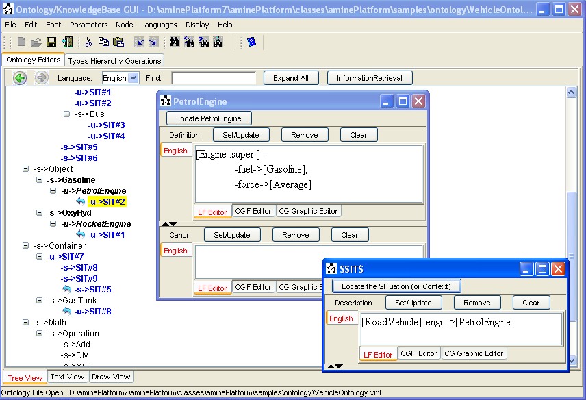
Figure 1: Ontology with Tree View (Editor)
The second possibility is to edit/consult ontology in Draw View Editor (Figure 2). Using graphical components (nodes for CSs and arrows for links), this view allows to use the same functions as those available in tree view mode. According to their category, nodes still appear in specific colours. Of course, the classical graphical operations are available (edition, selection, move, cut/copy/past, etc.) and any change made on either modes (addition, suppression, modification of nodes and/or links) affect directly the ontology and thus is visible in both modes. Also, user can zoom in/out the ontology, she/he can fix the vertical spacing between ontology nodes and she/he can find the localisation of a specific type or individual node in the ontology using the "Identifier" text field and the "Find" Button (Figure 2).
To produce a drawing view of an ontology (or a KB) from its tree view, we use the basic Sugiyama algorithm that enables an automatic drawing of a hierarchical graph (ontology in Figure 2 is automatically drawn).
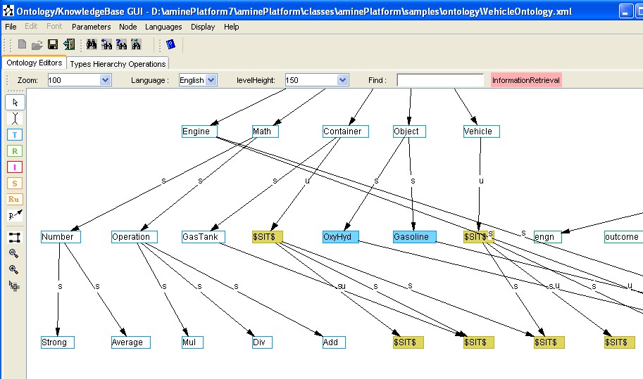
Figure 2: Ontology with Draw View (Editor)
In case of a very large ontology/KB, the user may have trouble reading it. To accommodate this problem, a Browser View Editor is provided that allows user to focus on a particular area of the ontology/KB. For instance, figure 3.a shows the browser view after selecting PretrolEngine node in Draw view and asking to focus on it in the Browser view. This allows getting the neighborhood of a particular node in the ontology. Then, functions "expand" and "collapse" allow user to perform selective browsing of the ontology by exploring neighborhood of any node in the Browser view. For example, figure 3.b illustrates the neighborhood expansion of the node "Gasoline" and of the SITuation node. With expand/collapse functions, user can perform selective browsing of her/his ontology.
|
(a) |
(b) |
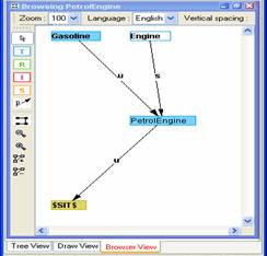
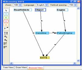
Figure 3: Ontology with Browser View (Editor)
Note: Currently, Ontology/KB GUI is restricted to ontologies with descriptions expressed in CGs. The current state of the GUI does not reflect the genericity of the Ontology API concerning the description scheme. Next versions will overcome this limitation.
Figure 1 shows the main frame of the interface. At the beginning, the user can either use the GUI for the edition of ontology or of KB. Figure 4.a illustrates this choice. Suppose that the user selects "Ontology", he/she can either open an existing ontology or create a new one. A new ontology is created in four steps:
Step 1: Choose the menu-action File/New (or click on the 'New File' Icon from the Icon bar). First, specify the languages that will be considered in your new ontology (Figure 4.b). Note that each ontology has its proper set of languages. Different ontologies can be defined with different set of languages. The initial set of languages can be updated later via the menu-action Languages/Update Ontology Languages (Figure 5). The user can then replace the name of an existing language, add another language or even delete an existing language (Figure 6).
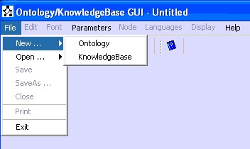
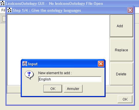
(a) Creation of Ontology or of KB (b) Step 1/4 in the creation of a new Ontology
Figure 4: New Ontology Creation, Step 1/4
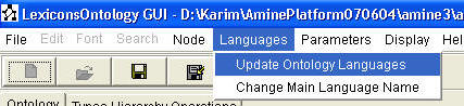
Figure 5 : Updating languages

Figure 6: Replacing a Language
Step 2: Choose the default language for your new ontology (Figure 7). Again, each ontology will have its proper main language. If a concept type (or relation type or individual referent) has no corresponding name in the current language then the system will use its name in the main language of the current ontology. Note that the main language can be changed later, via the menu “Languages/Change main Language” (Figures 4-6).
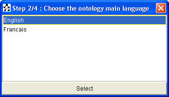
Figure 7: New Ontology Creation, Step 2/4
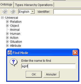
Step 3: Specify the identifier of the main root type of your new ontology, in the main language (Figure 8).
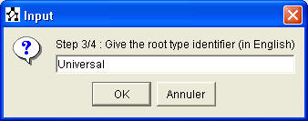
Figure 8: New Ontology Creation, Step 3/4
Step
4: Specify the identifier of the relation root type of
your new ontology (Figure 9). The relation root type is the concept type under which we store the
conceptual relations (agnt, obj, etc.). The relation root type is automatically added under the main root type.
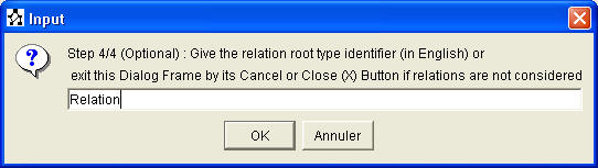
Figure 9: New Ontology Creation, Step 4/4
Now the user is able to define/update/edit/ask his/her ontology: Figure 10 shows the main frame of the ontology GUI. An ontology can be edited according to four views: tree view, text view, drawing view and browser view.
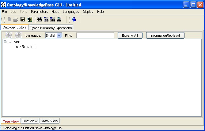
Figure 10: The ontology GUI
Let us mention that the ontology/KB GUI is associated with a Debug frame where all the error, warning, and information messages are displayed.
Opening and saving an ontology or a KB
It is possible to save the current ontology using the menu "File". We provide two options. The user can either save the ontology in a file with suffix ".ont", based on Java Serialization, or save it in XML format file with suffix ".xml". Once the ontology is saved, the name on the title bar changes automatically (Figure 11-13). To make your ontology portable, a cross the different versions of Amine and from Amine to other platforms and applications, it is better to save the ontology in XML format.
|
Figure 11: Saving an ontology 1/3 |
Figure 12: Saving an ontology 2/3
|

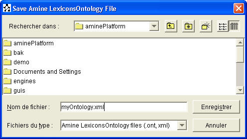
Figure 13: Saving an ontology 3/3
It is of course also possible to open an existing ontology, either using the ".ont" format or the XML format. The latter allows one to open an ontology created by another software or that has been edited in XML format or that has been created by a previous version of Amine (for these reasons, XML format is recommended).
The same holds for loading/saving KB.
Closing an ontology or a KB
The current ontology can
be closed by the menu "File/Close". In this case all the tabs
disappear from the screen (Figure 14). The user can then create a new ontology or
open an existing one.
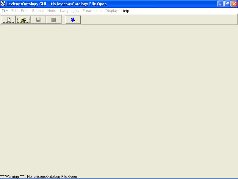
Figure 14:
Closing an ontology
Ontology/KB Editors I: Tree View Editor
The ontology/KB GUI provides two main facilities, organized in two tabs: Ontology Editors and Types Hierarchy Operations (Figure 15).
-
Define/Update/Edit the ontology (types hierarchy, conceptual structures, and lexicons) or the KB
-
Activate types hierarchy operations
Figure 15: The two Ontology facilities: Ontology and Type Hierarchy Operations Tabs
This section and the next two sections present Amine's Ontology/KB Editors (Tree View Editor, Draw View Editor, Browser View Editor). Types operations are introduced at the end of this document.
Tree View Editor
In the tree view, the ontology (or the KB) is presented as a tree and a node in the tree represents a Conceptual Structure (CS) node in the ontology/KB. The content of a node can be visualized, if required by the user, in a separate frame called "Content Frame" (Figure 16). Several "Content Frames" can be opened, one frame per node.

Figure 16: A CS Content Frame: a case of type Man
We will discuss first our solution to the problem of visualizing a graph as a tree! Indeed, an ontology (or a KB) can have a graph structure, not only a tree structure since an ontology/KB node can have several (direct) fathers.
Visualizing a Graph as a Tree
Let us mention that when the user inserts an
identifier/node that is already in the hierarchy, an identifier/node (Type or Individual) is then inserted and
the icon
![]() is added automatically to the new node to show that it
is an occurrence of an identifier/node that exists somewhere
else in the hierarchy. In this case the new added node is not inserted in the
ontology and it can not be explored; it is a reference to the first occurrence
of the same identifier/node. The new added node is only a
GUI/tree node and
not an ontology node. We call the first occurrence node
the Main Node and this node can be explored
(user can link to this node subTypes, individuals, situations, etc.). All the other
occurrences, that has the same name as the Main Node, are called
Reference Nodes and can not be explored.
Main Node/Reference Nodes is our solution for the representation of a graph
as a tree! Indeed, an ontology node N with several fathers will be
visualized by several tree nodes (one Main Node
and several Reference Nodes), each tree node presents N as a child of each
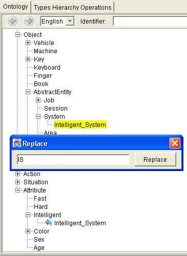
father. For example, the type 'Intelligent_System' has two super Types
'Intelligent' and 'System'. It is presented both as a child of System and of
Intelligent (Figure 17), the former is a Main Node while the second is a
Reference Node.
is added automatically to the new node to show that it
is an occurrence of an identifier/node that exists somewhere
else in the hierarchy. In this case the new added node is not inserted in the
ontology and it can not be explored; it is a reference to the first occurrence
of the same identifier/node. The new added node is only a
GUI/tree node and
not an ontology node. We call the first occurrence node
the Main Node and this node can be explored
(user can link to this node subTypes, individuals, situations, etc.). All the other
occurrences, that has the same name as the Main Node, are called
Reference Nodes and can not be explored.
Main Node/Reference Nodes is our solution for the representation of a graph
as a tree! Indeed, an ontology node N with several fathers will be
visualized by several tree nodes (one Main Node
and several Reference Nodes), each tree node presents N as a child of each
father. For example, the type 'Intelligent_System' has two super Types
'Intelligent' and 'System'. It is presented both as a child of System and of
Intelligent (Figure 17), the former is a Main Node while the second is a
Reference Node.
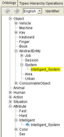
Figure 17: Node with more than one super Type
Actions on ontology nodes are provided via various popup menus, via the tool bar and via the Node menu from the menu Bar.
Select The Language for the Ontology/KB: The language list in the tool bar enables user to select the language in which the ontology/KB will be displayed (Figure 18).
Figure 18: Selection of the language
Change the language for the Ontology/KB: At any time, user can change the language and the display of the ontology/KB will change accordingly. For instance, in Figure 18bis, the ontology is displayed by default in English, since it was specified as the main language. Upon the selection of French, from the "language list", the ontology is then displayed, partially, in French (Figure 18bis). Partially because the user is not forced to specify the French name for each type and each individual. For any type or individual that has no name in French, Amine will use its name in the main language (English in this case).
 |
 |
Figure 18bis: Change the language for the ontology
Remark: Figure 18bis illustrates a new feature of the last version of Ontology/KB GUI: a node that has several direct parents is displayed in italic (like Human in Figure 18bis).
Expand All action: This action (via the button Expand All) enables the expansion of the tree (Figures 19 and 20).
Figure 19: Expand All (part I)
Figure 20: Expand All (part II)
Find action: It is possible to find a type or an individual using the find option of the popup menu or directly using Find button and the associated text field from the tool bar. While the user enter an identifier in the text field, the associated popup list shows the list of identifiers in the ontology that mach the input (Figure 21). Once the node is found, the hierarchy is expanded automatically to show the node that the user is looking for (Figure 22).

Figure 21: Find action using button Find (part I)
Here is another example of Find action, activated from the popup menu (Figure 22).
 |
 |
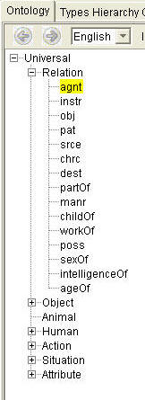 |
Figure 22: Finding a node using action Find from Popup menu
backward/forward buttons: The ontology/KB editor provides a facility that enables user to consult the sequence of actions in backward/forward manner. For instance, after asking for three different nodes, instead of finding them again, he/she has the possibility to use backward/forward buttons to go backward/forward to the nodes found in the previous steps (Figure 35).
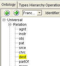
Figure 22bis: backward/forward buttons
Selection action: To define/edit a type hierarchy, the user selects the node he/she would like to edit. The selected node is highlighted with a yellow background (Figures 17). A right-click on a selected node will display a contextual popup menu that presents the available possibilities/actions depending on the type of the node (Figure 23). The user can also use the Node menu from the menu Bar. These possibilities/actions are introduced below.
Contextual PopUp menus
The PopUp menu the user gets with a right-click is contextual, it depends on the selected GUI node. It depends in particular on the type of the node: there is a category of popup menus for Main Node and a popup menu for Reference Node. In the case of main node, the GUI provides popup menus for Type, Individual, Situation and CSRule nodes.
Reference Node PopUp Menu: The popup the user gets for a Reference node contains five options/actions (Figure 23.a): "GoTo Next Occurrence" to go to one of the other Reference nodes, "Show/Edit Content" to show the content, "SuperTypes" to show the superTypes, "Remove Link from father" to remove the link between the node and the father, and finally "GoTo First Occurrence" to go to the main node with the same name in case we want to explore its children for instance.

(a) Popup menu for referent node (b) Popup menu for main node
Figure 23: Popup menus of Reference & Main Node
Type Node PopUp Menu: The popup the user gets for a Type node contains eight options/actions (Figure 23.b): GoTo Next Occurrence to go to another occurrence of the selected node if the node has more than one father, Show/Edit Content to show/edit the description of the selected node, SuperTypes to show the superTypes of the selected node, Find to locate a node in the tree, Edit to edit the identifier of the selected node, Synonyms to edit the synonyms associated to the selected node, Insert to add a node or a link with the selected node as the source node, and Remove to remove the selected node or to reove the link that relates the selected node to its parent.
Situation Node PopUp Menu: In the popup of a situation node (Figure 24), Edit and Synonyms options are disabled.
Figure 24: Popup of a situation Node
GoToNext Occurrence action: In case you have more than one node with the same name and you don't know where the other GUI/tree nodes are located, the user can go from the current occurrence to another occurrence by applying the GoTo Next Occurrence action (Figure 25).
 |
 |
Figure 25: Using the GoTo Next Occurrence action
GoTo First Occurrence action: this action, from the reference node popup menu (Figure 23.a), enables the user to go to the first occurrence of the node, the main node, in case we want to explore its children for instance, or to change its identifier.
Edit action: It is also possible to edit the current node by applying the Edit option/action from the popup menu. The change is spread to all the GUI/tree nodes that have the same name (Figure 26).
 |
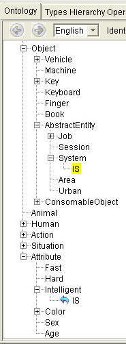 |
Figure 26: Using the Rename option
SuperType action: In case a node has more than one super type, we can use the SuperTypes option, from the popup menu, to know all the super types of a node (Figure 27). It enables a (partial) bottom-up browsing of the ontology.
 |
 |
Figure 27: Using the SuperTypes option
Insert action: Insert action provides two possibilities: a) insertion/addition of a new CS node (a new Type, a new Individual, a new Situation or a new CSRule) as a new child for the selected node, b) addition of a new link to an existing CS node (Figure 28).
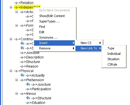
Figure 28: Inserting a new Node or a new Link
Insert a new subtype for the selected node: select Insert/New CS/Type (Figure 29). He/She is then asked to provide the name of the new subtype (Figure 29). The new subtype is then added as a new subtype of the selected node. Once the Type node is added, user can activate "Show/Edit Content" action in order to provide its definition and/or canon. This action is introduced below.


Figure 29: Inserting a new Type
Insert a new individual/instance for the selected node: select Insert/New CS/Individual (Figure 30). He/She is then asked to provide the name of the new individual (Figure 30). The new individual is then added as a new individual of the selected node. To distinguich individuals from types, the String (IND) is added automatically and the individual name is displayed with the color Magenta (Figure 30). Once the Individual node is added, user can activate "Show/Edit Content" action to provide its description. This action is introduced below.


Figure 30: Inserting a new Individual
Insert a new situation for the selected node: select Insert/New CS/Situation (Figure 31). To distinguich the situations from the types, the String (SIT) is added automatically with the color Blue. Note that no name is displayed for a situation, except the name generated automatically by Amine. Once the Situation node is added, user should activate "Show/Edit Content" action in order to provide its description. This action is introduced below.
Figure 31: Inserting a new Situation
Insert a new CSRule for the selected node (Figure 31.b): insertion of a new CSRule is similar to insertion of Situation.

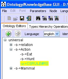
Figure 31.b: Inserting a new CSRule
Remove action: Like Insert, Remove action provides two possibilities: a) Remove a CS node, b) Remove a link .
Remove/Node action: The node is removed from the ontology and all the corresponding GUI nodes are also removed (First node and reference nodes), (Figure 32). Note that a node can be removed only if it has no child.
 |
 |
Figure 32: Removing a CS node from the ontology
Remove/Link action: Remove the link between a father and one of its children in the ontology: the user selects one node and with a right-click, he/she selects the option Remove/Link from Father which removes the link between the selected node and its father. For example, in Figure 33, the user wants to remove the link from Form to Schema. The two nodes (Form and Schema) are not removed from the Ontology, only the link is removed.
 |
 |
Figure 33: Removing a link from one node to its father
Synonyms action: This action (Figure 34.a) enables the user to edit synonyms, in the current language for a specified type or individual as well as synonyms in other languages. Edition of synonyms is done in a separate frame titled "Edit Synonyms" (Figure 34.b). To get synonyms of the selected node in the current language, the user has to select button/action Get (Figures 34.b & 34.c). Figure 34.c shows the result: specification of a synonym (Person) of the type “Human” in the English language. To get synonyms of the selected node in all languages (associated to the ontology), the user has to select button/action Get All (Figure 34.d). Figure 34.d shows the result.
 (a) Edit Synonyms Button/action |
 (b) Edit Synonyms Frame |
 (c) Get and the result |
 (d) Get All and the result |
Figure 34: Synonyms of Human in English (the button/action Get) and in all languages (the button/action Get All)
After displaying all synonyms of Human in all languages (Figure 34.d), user may want to add for instance a new synonym in French, let us say "Etre_Humain". In this case, He/She has to clear the content of the "list of synonyms", with the button/action Clear (Figure 35.a), select the language French from the "synonyms language" list (Figure 35.b), and then activate the button/action Add (Figure 35.c). This action displays an input dialog frame where the user has to enter the new synonym (Figure 35.c). Then, the user has to activate button/action Set (Figure 35.d).
 (a) Clear |
 (b) Select language |
 (c) Add & Enter name |
 (d) Set to add the synonym in the lexicon |
Figure 35: Addition of a new Synonym
To modify a synonym S in a language L, the user has to clear the content of the "list of synonyms" and then get the synonyms in L with button "Get >>". Then, he/she has to select the synonym S and select the button "Replace". After the modification, the synonym will be replaced.
The same scenario should be used to delete a synonym.
Show/Edit Content action: Edition of Node (Conceptual Structures; CS) Descriptions
To be able to specify/consult/edit the "content" of a node (type definition and canon, individual description, situation and CSRule description), the user has to left double click on the node or he/she has to calls the popup menu from the selected node and selects the Show/Edit Content option. The content of the node is displayed in a separate frame. For a type node, its content frame is split in two parts (Figure 36.a for type Man): The top part is for the definition (if any) while the bottom part for the canon (if any). When the user selects Show/Edit Content for an individual or a situation node, its content frame (Figure 36.a) contains the specification of the description (if any). Several content frames can be displayed (Figure 36.a). Figure 36.b provides an example of a content frame for a CSRule.
(a) Content frames for Type and Situation nodes

(b) Content frames for CSRule
Figure 36: Content frames for Type, Situation and CSRule nodes
The description (a CG) is displayed/specified using the embedded CG multi-lingua and multi-view Editor of Amine Platform. After the edition of the description associated to a node, the user can add it to the ontology/KB using Set/Update button. The user has also the possibility to remove the description of the node using the Remove button, and the possibility to clear the content of the CG editors using the Clear button.
During the edition of a description of a CS node, user can browse and edit the ontology. He/she can use Find button to find specific types or individuals, to change the identifier of a node, to add new nodes, to request for or adds synonyms, etc. Note that changes in the ontology will be notified by the CG editors; the change of an identifier (of a concept type, a relation type, or an individual), the addition of a synonym will be notified and considered immediately. For instance, the change of the relation identifier "obj" to "objct" will involve a change of "obj" to "objct" in any edited CG that contains this relation.
Locate *** Type/Individual *** button/action: After several Find actions and other browsing actions, user can forget the node for which the content is displayed in a "CS Content Frame" ! To remind the user of this node, Ontology GUI provides a button at the left-top of each CS Content Frame, where the name of the node is displayed. For instance, in Figure 37.a, the content frame for type PelicanScientist has a button at the top-left side: "Locate PelicanScientist". Upon a click on this button, the node is located and displayed in the ontology "tree view" (Figure 37.b).

(a) activation of button "Locate PelicanScientist"
(b) The CS node for PelicanScientist is localized in the ontology and highlighted
Figure 37: Locate the CS node in the Ontology
Locate the SITuation (or Context) button/action: The same treatment occurs for the case of situation (which has no name); the button at the top-left side of the content frame has the label "Locate the SITuation (or Context)" (Figures 36-37). Its activation enables the localization of the Situation node in the ontology.
Ontology/KB Editors II: Draw View Editor
In the draw view, the ontology/KB is presented as a graph with one root: the "root type". A node in the graph is visualized as a rectangle and it represents a Conceptual Structure (CS) node in the ontology/KB. As in the tree view editor, the content of a node can be visualized, if required by the user, in a separate frame "Content Frame". Several "Content Frames" can be opened, one frame per node (Figure 38).
All operations/actions provided by tree view editor are also provided in draw view editor. Also, any change in one view (addition, deletion, update of nodes, etc.), will have an impact in the other views. In addition, Draw View Editor provides: a) Zooming facilities, b) the possibility to change vertical spacing (vertical distance between two levels), c) automatic drawing of the graph (rearrange button/action), and d) making a focus on a specific node in order to perform a selective browsing of its neighborhood.
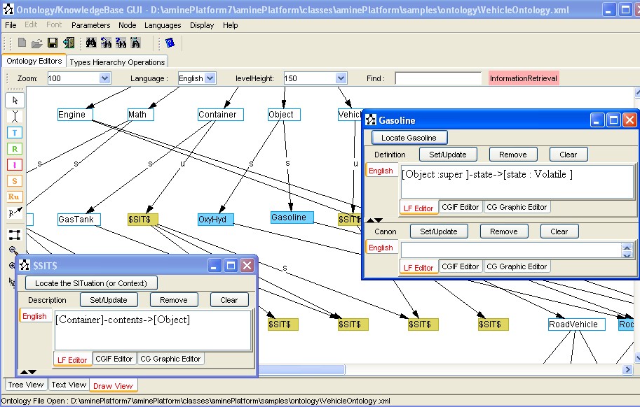
Figure 38: Locate the CS node in the Ontology
Select The Language for the Ontology/KB and Change the language for the Ontology/KB are identical to tree view editor.
Find action: Find button/action and the associated text field in the tool bar, enables the localization of the node in the ontology. Figure 39 illustrates this action in draw view.
(a) Find the node for RoadVehicle
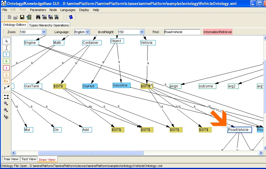
(b) the node for RoadVehicle is located in the ontology
Figure 39: Find a node in the ontology
Change of Vertical Spacing action: distance between levels can be changed. the "Vertical spacing list" in the tool bar provides possible values (Figure 40).

Figure 40: Change of vertical spacing
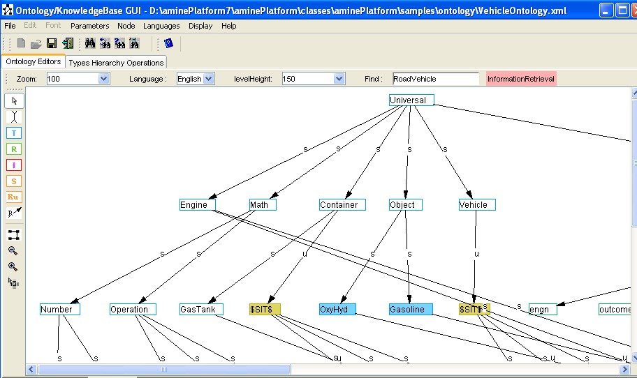
Zooming action: User can increase or decrease the zooming of the drawing graph (Figure 41). User can select a zooming factor from the "Zoom list" in the horizontal tool bar, or directly using the two buttons/icons for "increase zooming" and "decrease zooming" in the left vertical tool bar.
(a) Zoom at 100%
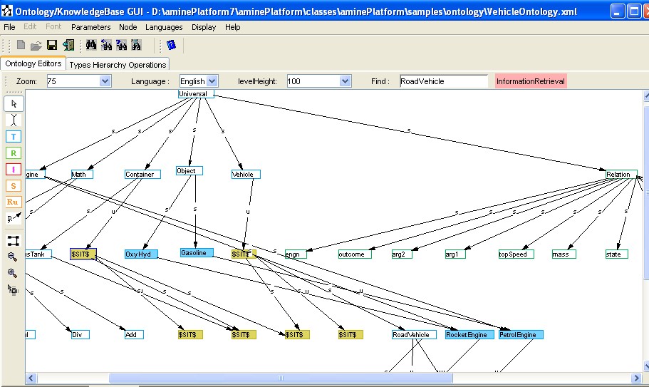
(b) decrease in zooming: zoom at 75%
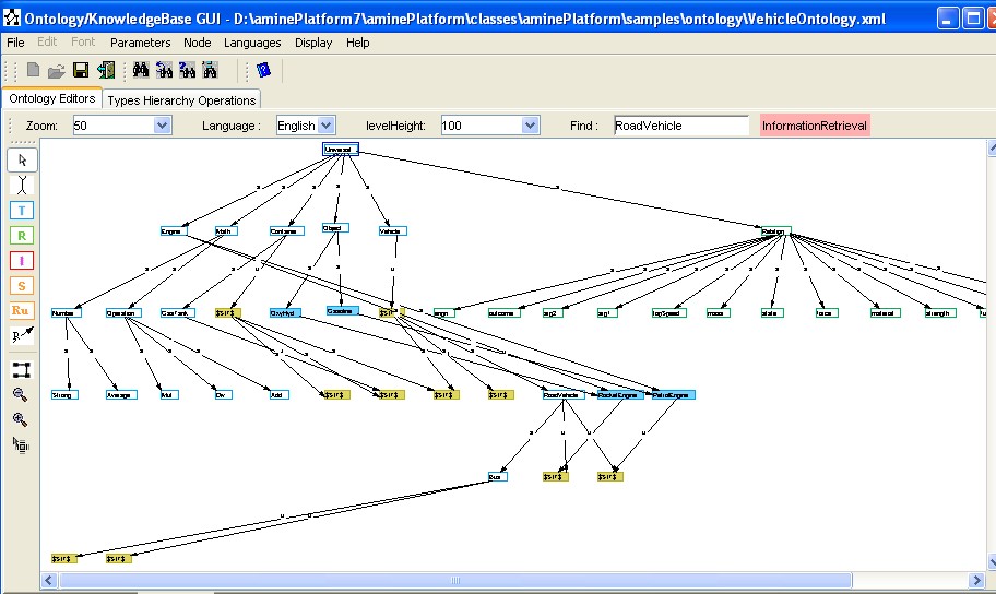
(c) decrease in zooming: zoom at 50%
(d) increase in zooming: zoom at 150%
Figure 41: Decrease/Increase in Zooming
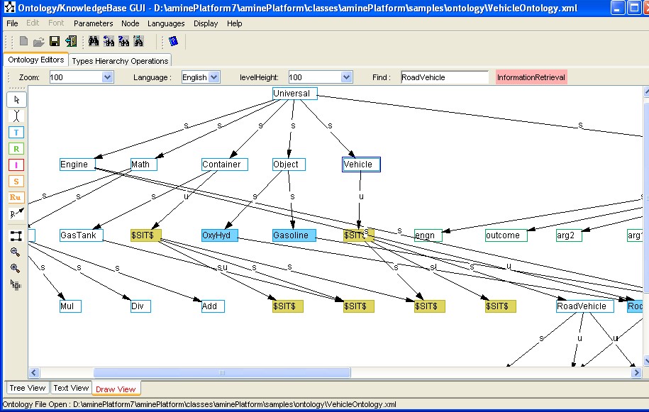
Rearrange (automatic drawing) action: At any time, user can activate button/action rearrange to initiate automatic drawing of the current ontology. This call can be done for instance after some modifications have been done to the ontology. Figure 42 provides an example.
(a) state of the Ontology before activation of button/action "ReArrange"
(b) state of the Ontology after activation of button/action "ReArrange"
Figure 42: Rearrange the drawing of the current Ontology (automatic drawing)
"Switch to Browser View" action: To perform located and selective browsing of the ontology, starting with a specific node, user has activate "Switch to Browser View" button/action (Figure 43.a). Then, left click on the node from which he/she wants to start the selective browsing (Figure 43.b). After the click, Amine provides the "Browser View Editor" (Figure 43.c). See below for more detail on this view.
(a) activate "Focus in Browser" button (b) left click on the node to start browsing (c) Neighborhood of the selected node in
Browser View Editor
Figure 43: Switch to Browser View Editor
Drawing of the four types of nodes: The left vertical tool bar provides several buttons for the edition of an ontology ("ReArrange" and "Zoom" buttons have been introduced before). It provides four buttons/icons for the drawing of the four types of CS nodes: Type node, Relation Type node, Individual node and Situation/Schema node (Figure 44.a). It provides also a button/icon for drawing a link between two nodes, a button for "Command mode" and a button/icon for "Text Cursor" (i.e. for the edition of the node's name). The general popup menu (displayed after a right click on an empty space in the draw view editor) (Figure 44.b) provides the four types of CS nodes (to insert any one of these types of nodes at the location of the right click). Also, if a node has no description, it is visualized as an "empty node", if it has a description, it is visualized as a "filled node" (Figure 44.c). This difference enables the user to "see" which node has a description and which one has not.

![]()
(a) Buttons/Icons for the four types of CS nodes (b) The four types from the popup menu (c) "empty node" vs "filled node"
Figure 44: Buttons for the edition of the CS nodes
Note: Since Amine 5.0, a new button has been added for the new CS: CSRule (Figure 44.b).
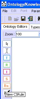
Figure 44.b
Insertion of a new type/relation node: Let us consider now the steps for the insertion of a new type (i.e. Road) that is a subtype of a type that exists already (i.e. Object): a) select/activate the "Type node" button/activation from the left vertical tool bar, click at the desired location (Figure 45.a), a text field will be displayed in order to provide the type's name (Figure 45.a), press "enter" key to finish the edition of the name and then the text field is replaced by rectangle that encloses the string (Figure 45.b). Now, user has to connect the node "Object" with the new node "Road" by a specialization link. To do that, user has to select/activate the "Link" button/action from the left vertical tool bar, left click on the source node ("Object" in this case) and then left click on the target node ("Road" in this case) (Figure 45.c). A text field will be displayed in order to provide the type of the link (specialization, individual or usedIn) (Figures 45.d & e). Press "enter" key to finish the edition of the name and then the text field is replaced by the string that represents the type of the link (Figure 45.e). Note that only three types of links are allowed in an ontology: specialization, individual or usedIn. After that, user can specify a content for the new type (see below).
Exactly the same steps are required for the insertion of a new relation type node, with of course the selection/action of the "Relation node" button (instead of "Type node").
(a) Enter the name of the new type (b) the new type as a new node (c) Link the new type to its superType
(d) Select the type of the link (e) the new type is connected to its superType
Figure 45: Insertion of a new Type node
Insertion of a new individual node: Let us consider now the steps for the insertion of a new individual (i.e. GasTank23) that is an individual of a type that exists already (i.e. GasTank): a) select/activate the "Individual node" button/activation from the left vertical tool bar, click at the desired location (Figure 46.a), a text field will be displayed in order to provide the individual's name (Figure 46.a), press "enter" key to finish the edition of the name (Figure 46.b). An input dialog window is displayed asking for the type of the new individual (Figure 46.b). After entering the type's name and selecting/activating "OK" button, the new individual node is added, connected to its type and placed automatically by the drawing editor (Figure 46.c). After that, user can specify a content for the new individual (see below)
(a) Enter the name of the (b) Provide the type of the individual (c) the new individual node is added and placed automatically
new individual
Figure 46: Insertion of a new Individual node
Insertion of a new situation node: a) select/activate the "Situation node" button/activation from the left vertical tool bar, click at the desired location (Figure 47.a), a new situation node will be displayed (Figure 47.a), b) connect the new node to the desired type with an "u" link. The result is displayed in Figure 47.b. After that, user can specify a content for the new situation (see below).


(a) add and place the new situation node (b) connect the new situation node to the type with the "u" link
Figure 47: Insertion of a new Situation node
Show/Edit the content of a CS node: Figure 48 illustrates this action in the case of a type (i.e. Road). Similar steps are required for relation, individual and situation nodes: a) select and right click on the desired node, and select "Show/Edit Content" action (Figure 48.a). A CS content frame is displayed to enter the specification of the selected node (Figure 48.b).

(a) Select "Show/Edit Content" action (b) CS Content Frame is displayed to enter Road specification
Figure 48: Specification of the content of a CS node
Edit the name of a CS node: To edit (modify) the name of a Type node, a RelationType node or an Individual node, user has to select/activate the "Text Cursor" button from the left vertical tool bar, and then left click on the desired node. A text field will be displayed at the place of the node. Then user can edit the name of the node. Once the edition finished, user should tape "enter" key. The text field will be replaced by a rectangle that encloses the name.
Popup menus of Draw View Editor: Draw Editor View provides three popup menus: a) general popup menu (Figure 49.a) displayed after a right click on an empty space, b) CS node popup menu that provides some basic actions on the selected CS node (Figure 49.b), c) link node popup menu that provides two actions on a link: cut and edit (Figure 49.c).

(a) general popup menu (b) CS node popup menu (c) link popup menu
Figure 49: Popup menus of Draw View Editor
Actions in General popup menu: a) edition actions: "Paste" a node (copied before) at the location of the click, "Clear All" the draw editor panel, and "Select All" the content of draw editor, b) insertion actions: Insert Concept type, Relation Type, Individual or Situation node, Insert a link ("New Edge" action), c) "Auto-arrange" to initiate automatic drawing (or update of the drawing of the ontology).
Actions in CS node popup menu: a) edition actions: "Cut" the selected node, "Copy" the selected node, "Edit" the name of the node, "Show/Edit Content" of the selected node, edit "Synonyms" of the selected node, b) Switch to the Browser View Editor and "Focus in Browser" on the selected node.
Actions in CS node popup menu: "Cut" the selected link and "Edit" the name of the selected link.
Graph edition operations and facilities : the main actions of a graph drawing editor are provided by the Ontology draw view editor: create and put/place a node at a desired location (using the mouse), move (with mouse drag action) a selected node or a selected subgraph at any location, edit a node, cut/copy/past a selected node, remove a node (with remove action or a press on the "suppr" key from the keyboard), remove a link, etc.
Special treatment is done for copy/past of a CS node: it corresponds to a deep copy: both the name and the content is copied (cloned). Figure 50 provides an example: a) activate a Copy of the selected node (Figure 50.a), Paste the copy at the desired position (Figure 50.b). A new node will done be displayed (Figure 50.c). The name NAME of the copy of the node is copied in "$$NAME$$", like "PetrolEngine" in "$$PetrolEngine$$" (Figure 50.c). Of course, no two nodes can have the same name, that is why the copy is in the form "$$NAME$$"; user should edit the new node to change its temporary name (Figure 50.d). Figure 50.c shows also the content of the copy. User can edit such a content to suite his need.
(a) select Copy of the selected node (b) Paste the node at the desired position
(c) The new copy of the selected node with its content (d) Edition of the name of the copy
Figure 50: Copy/Paste of a CS node
Ontology/KB Editors III: Browser View Editor
As noted before, in case of a very large ontology/KB, the user may have trouble reading the ontology/KB. To accommodate this problem, a Browser View Editor is provided that allows user to focus on a particular part of the ontology/KB. The Browser editor provides possibility for performing selective browsing and a possibility to define a partial view of the ontology/KB. The Browser allows getting the neighborhood of a particular node in the ontology/KB. Then, actions "expand" and "collapse", initiated by the two buttons in left vertical tool bar (Figure 51.a), allow user to perform selective browsing of the ontology/KB by exploring neighborhood of any node in the Browser view (Figure 51.b). Let us consider the example illustrated in Figure 51: From "Draw View" editor, user selects "Focus in Browser" button and then left click on node "Engine". The "Browser View editor" is added and becomes the current editor (Figure 51.a). Only a very small view (of the ontology) is displayed in the Browser: the selected node (in this case: Engine node) and its neighborhood: its fathers and children (Figure 51.a). The user can explore this small view of the ontology by activating Expand button on any node in the Browser (bold name in a node means that the node has fathers and/or children). For instance, Figure 51.b illustrates the selection of Expand button and then selection of node "RocketEngine". This node has been expanded as illustrated by Figure 51.b. Successive use of Expand enables selective expansion/exploration of the current view.
Figure 51: Browser View Editor and Expand action
Collapse is the inverse operation of Expand. It is illustrated in Figure 52: Collapse action is performed first on node "PetrolEngine": the result is the hiding of its child (Figure 52.b). Then the same action is performed on node "RocketEngine": the result is the hiding of its child (Figure 52.c).

(a) initial state of the Browser view (b) Application of Collapse action on PetrolEngine node (c) Application of Collapse on RocketEngine node
Figure 52: Collapse action
Ontology/KB Editors IV: Ontology Text View Editor
The last ontology editor, available with Amine 6.0, is a textual editor that provides the possibility for a textual description of an ontology, and especially the "kernel" of the ontology (i.e. type hierarchy and individuals). Tree editor or draw editor can be used to extend the ontology with types definitions, situations descriptions, synonyms specification, etc.
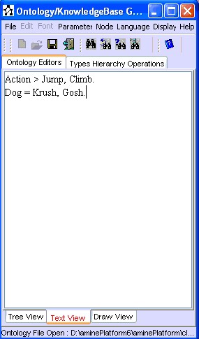
The user of "Ontology Textual View Editor" can use two types of statements to add information to a new or an existing ontology: a) Type/Subtypes statement which specifies a list of new subtypes for an existing type (new subtypes identifiers are separated by comma and the succession terminates with a dot. The type identifier and the list of new subtypes identifiers are separated by the symbol ">"), b) Type/Individuals statement which specifies a list of new individuals for an existing type (new individuals identifiers are separated by comma and the succession terminates with a dot. The type identifier and the list of new individuals identifiers are separated by the symbol "=").
(a) Type/Subtypes statement:
TypeIdentifier > NewSubType1, NewSubType2, ..., NewSubTypeN.
Example:
Universal > Action, Object, Person, Proposition.
Action > Drive, Drink, Eat, Walk, Think.
Person > Man, Woman.
(b) Type/Individuals statement:
TypeIdentifier = NewIndividual1, NewIndividual2, ..., NewIndividualK.
Example:
Man = John, Smith, Bernard, Joel.
Woman = Mary, Catherine, Carole.
Ontology Text view editor can be used for the creation of the kernel of a new ontology, or it can be used for the extension of an ontology that exists already. Ontology Text View Editor can be viewed as an "easy and rapid way" to introduce type/subtypes and type/individuals information, instead of the "long way" provided by Tree View Editor and Draw View Editor.
Let us consider now some examples to illustrate the use of this new editor (since Amine 6.0).
Example 1:
This example illustrates the use of the "ontology text view editor" starting with the creation of a new ontology. Like the other editors, creation of a new ontology starts with the four steps (see Getting Started): a) specification of the languages, b) specification of the main language, c) specification of the root for concept types, d) specification of the root for relation types. Now, the new ontology contains only two types/nodes: the root of concept types and the root of relation types. Let us assume that the user has provided the identifier "Universal" for the root of concept types and the identifier "Relation" for the root of relation types. Figure 53.a shows the state of this new ontology (with the tree view editor). Now, user can select and use ontology text view editor to add new information to the new ontology. This is illustrated by Figure 53.b.
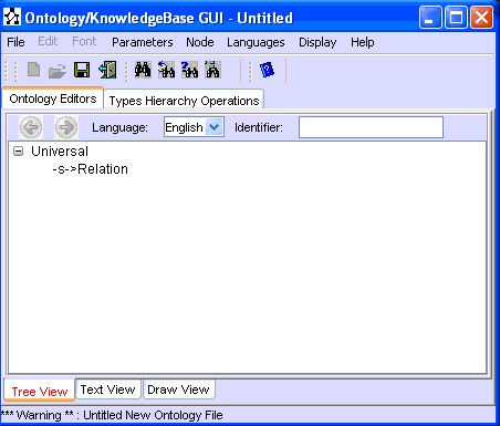

(a) The initial state of the new ontology (with Tree View) (b) Use of Text View: addition of new information to the current ontology
Figure 53: Ontology Text View Editor
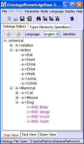
Selection of Tree View Editor/Tab (or of Draw View Editor/Tab) will initiate a parsing of the text (in the Text View Editor/Tab) and then the "execution of the statements": addition of the new information to the internal representation of the ontology. Figure 54 shows the result after the selection of the Tree View.
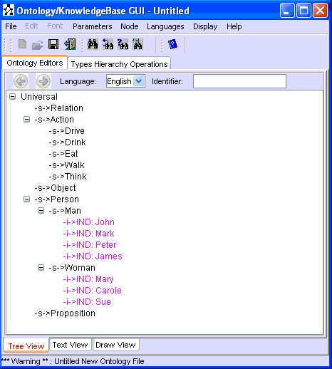
Figure 54: Selection of Tree View Editor after the use of Text View Editor
Example 2:
This example illustrates the use of the "ontology text view editor" to add information to an existing ontology. For instance, Figure 55.a shows the result of loading/opening the ontology "CatMouse.xml" (with Tree View Editor). Ontology text view editor is then used to specify some statements that will add information to the existing ontology (Figure 55.b). Then, selection of Tree View Editor shows that the statements have been executed and information has been added to the existing ontology (Figure 55.c).
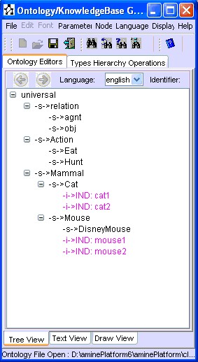
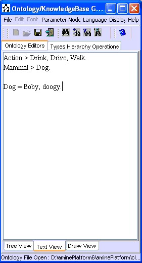

(a) Open an Ontology in Tree View Editor (b) Use of Text View to add new information to the current ontology (c) Content of Tree View is updated
Figure 55: Edition of an existing ontology
User can delete all the content of Text View Editor in order to introduce new information. For instance, content of Text View Editor in Figure 55.b is deleted and new statements are specified (Figure 56.a). Selection of Tree View Editor shows the result of such an update (Figure 56.b).
As noted before, Ontology Text View Editor can be viewed as an "easy/rapid way" to introduce type/subtypes and type/individuals information, instead of the "long way" provided by Tree View Editor and Draw View Editor.
(a) Delete and specify a new content in Text View editor (b) Content of Tree View is updated
Figure 56: Edition of an existing ontology (continue)
Save/Load the content of Text View Editor
The content of Ontology Text View Editor can be saved and loaded. It is saved as a text with "ontxt" or "txt" extensions. Figure 57 illustrates the save case. Note that only the content of "Text View" which is saved (as text), not the whole ontology.
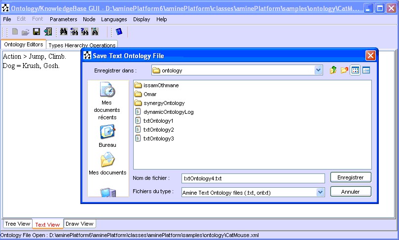
Figure 57: Save the content of the "Ontology Text View Editor"
Figure 58 illustrates the load case. Note that the action "TextOntology" has been added to the "Open" menu, and it is enabled only when the current ontology editor is "Text View" editor. Note also that what is loaded is not the whole ontology, but only the content of the text file.


Figure 58: Load in the "Ontology Text View Editor"
The "Find" option finds and locates the node (type node or individual node) with the specified identifier. Information Retrieval is of course more general. When the button "Information Retrieval" is activated, the window dialog is provided to the user: he/she can search for a type with a specified definition, or search for a situation with a specified description, or search for a rule with a specified description (Figure 58bis1).

Figure 58bis1: Information Retrieval facility
If a node exists in the ontology that responds to the conditions of the request, it is located in the ontology. Let us consider the following example: consider the Question: "Does the current ontology contains a type with the following definition: [Human]-sexOf->[Sex: male] ?". After selection of "Definition" (see Figure 58bis1), the system provides a window (Definition Information Retrieval) where the user has to specify the definition, and then asks the user for pertinent types for the specified definition (Figure 58bis2).
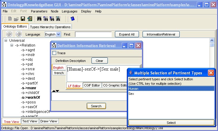
Figure 58bis2: Search for a type with the specified definition
As a result of the search, the system finds that the ontology contains the type "Man" with the specified definition (Figure 58bis3).
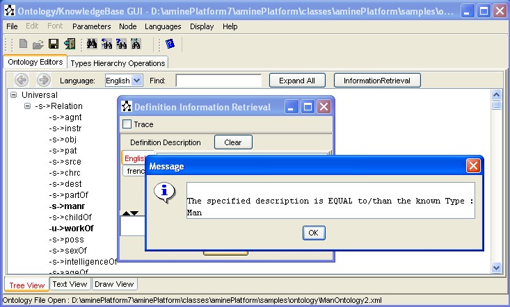
Figure 58bis3: Search for a type with the specified definition
... and then locate the node "Man" in the ontology (Figure 58bis4).
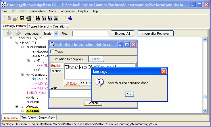
Figure 58bis4: The node is located in Tree View
... and if the user switchs to "Draw View", he/she will find that the node "Man" is also located in this view (Figure 58bis5).
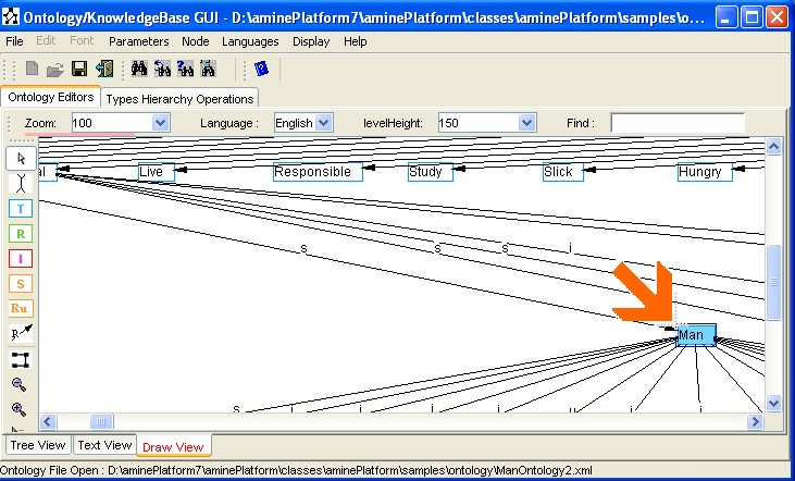
Figure 58bis5: The node is located in Draw View
See Information Retrieval for more detail on Information Retrieval facility.
Edition of an Ontology with Synergy Primitives
To edit an Ontology with Synergy Primitives (an ontology that contains Synergy Primitives), user should load first the ontology for Synergy Primitives. This predefined ontology constitutes the ontological background for this kind of ontologies. Here is an example that illustrates this point:
The ontology "ontology1.xml" (stored in aminePlatform/samples/ontology/synergyOntology/) contains Synergy Primitives. So, before opening this ontology with Ontology/KB GUI, the user should load first Synergy Ontology (i.e. the predefined ontology for Synergy Primitives). To do this, the user has to select the action menu "Load First Synergy Ontology" from the menu "Parameters". Then, open the ontology "ontology1.xml" (Figure 59).
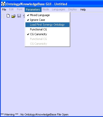

Figure 59: Load Ontology with Synergy Primitives
This tab provides several operations concerning type hierarchy (Figure 60). Some operations are monadic (DirectSubTypes, DirectSuperTypes, AllSubTypes, AllSuperTypes) while others are dyadic (IsSubType, IsSuperType, MaximalCommonSubType and MinimalCommonSuperType). The result of the operation is displayed in the field under the label “Result”.
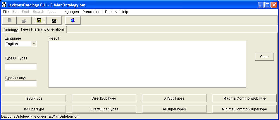
Figure 60: Types hierarchy operations Tab
Suppose we use the
type hierarchy described in Figure 61:
|
|
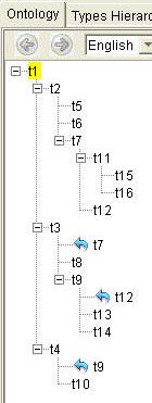 |
Figure 61: Example of Type hierarchy
Figure
62 shows
the call of isSubType operation. The GUI checks if Type1 t7 is SubType of Type2
t1. The boolean result is displayed in the Result field.
Note the last check where Type2 is "t22":
since "t22" does not exist in the type hierarchy, the system returns a message in
the Debug Frame.
|
|
|
|
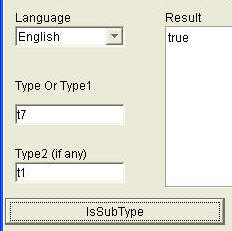


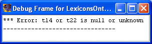
Figure 62: Examples of IsSubType Operation
The activation of the other operations follows the same steps. If the operation is monadic, the field "Type2 (if any)" is not used.
